A valve guide is cheap until the bore closes after pressing, the stem starts to stick, or an aluminium head loses retention after heat cycles. For sourcing teams, valve guide dimensions are not a catalogue line item. They are a control plan: outside diameter, inside diameter, length, concentricity, seal land, chamfer geometry, material and the measurement state all need to be defined. Loose-guide measurements can be misleading because installation changes the bore. A 0.02 mm error in interference can create movement, distortion or unstable running clearance. This note reframes the specification as a purchasing decision: what to lock on the drawing, what to validate after installation, where failure modes start, and how MOQ, price and lead time change when the part moves from catalogue supply to engineered production. Driventus is an independent aftermarket manufacturer; brand names are referenced for fitment only.
Decision framework: what must be locked before RFQ
Start with the surfaces that decide whether the guide stays in the head, supports the stem and meters oil. Do not issue an RFQ that says only “standard size” or lists an application name. Cylinder head material, rebuild method and regional repair practice can all change the correct valve guide dimensions.
Use this hierarchy when building the drawing:
Field
What to specify
Why it matters in sourcing
Overall length
30–70 mm typical passenger car range; 45–110 mm for many commercial-duty heads
Sets installed height, port exposure and spring-side clearance
Outside diameter
Nominal OD plus press-fit tolerance, commonly 0.01–0.06 mm interference depending on head material
Controls retention, insertion force and post-press bore shape
Inside diameter before finishing
As-supplied bore size, often 0.01–0.04 mm undersize on semi-finished parts
Prevents confusion between loose-part ID and final working clearance
Finished inside diameter
Valve stem diameter plus running clearance, often 0.015–0.050 mm depending on stem size and duty
Defines the actual oil, wear and seizure window
Concentricity
OD-to-ID relationship, typically 0.01–0.03 mm target for service parts
Protects seat alignment and even guide wear
Chamfer / lead-in
Angle and depth on each end, often 30°–45° and 0.3–1.0 mm depth
Reduces shaving, cracking and press damage
Groove or seal land
Width, position and diameter; commonly 1.0–2.5 mm land width where stem seals sit
Must match the seal and installed height
Surface roughness
OD, ID and seal land finish requirements
Affects insertion force, lubrication and stem wear
</tr></thead><tbody> </tbody></table>For catalogue demand, Driventus can cross-reference buyer drawings and application data against our catalog. For engineered demand, custom manufacturing can start from a 2D drawing, 3D model, sample or controlled OE-style reference such as OE 06A… where the buyer already uses that convention.
The RFQ should also state annual demand, initial order quantity, target release schedule and documentation level. If PPAP-style evidence is needed, say whether it is required at first submission or only after commercial award.
Spec deep-dive: tolerances that change after pressing
The most important question is not only “what is the bore?” It is “when is the bore measured?” A valve guide can meet print as a loose part and still fail after installation because press fit changes roundness and ID.
Practical starting ranges for sourcing specifications:
Parameter
Common range
Typical control target
Outside diameter tolerance
Nominal ±0.005 to ±0.015 mm; many aftermarket programmes accept ±0.010 mm on small bores and ±0.015 mm on larger bores
Based on required interference and head material
Inside diameter tolerance, finished
Nominal ±0.005 to ±0.010 mm
Verified after installation where applicable
OD roundness
≤0.005 mm
Prevents uneven press load and local stress
ID roundness
≤0.005–0.008 mm
Supports stable stem clearance and oil control
OD/ID concentricity
≤0.015–0.030 mm
Lower values for high-speed or low-emission engines
Length tolerance
±0.05 to ±0.15 mm
Depends on seal, spring and port geometry
Chamfer depth
0.3–1.0 mm typical
Confirm both ends if the guide is asymmetric
Surface roughness, bore
Ra 0.4–1.6 µm typical; performance stems often call for Ra ≤0.8 µm
Depends on material, lubricant and stem finish
</tr></thead><tbody> </tbody></table>Treat interference fit as a purchasing-critical dimension. Aluminium heads and cast iron heads do not behave the same. Thermal expansion, bore deformation and insertion force differ, so the RFQ should state head material, finished head bore diameter, target interference, installation temperature if the head is heated, and whether the guide is chilled before pressing.
As a working rule, many repair programmes begin around 0.02–0.05 mm interference for smaller aluminium-head guides and 0.03–0.06 mm for larger or higher-load applications. Those numbers still need validation by press force and installed bore stability.
Separate finished running clearance from the as-supplied ID. Many rebuilders buy semi-finished guides, press them into the head, then ream or hone to final size. That sequence compensates for shrinkage or distortion. Typical target clearance is often 0.02–0.05 mm for intake guides and 0.03–0.07 mm for exhaust guides on common passenger-car platforms, but final limits must follow stem diameter, lubrication and duty cycle.
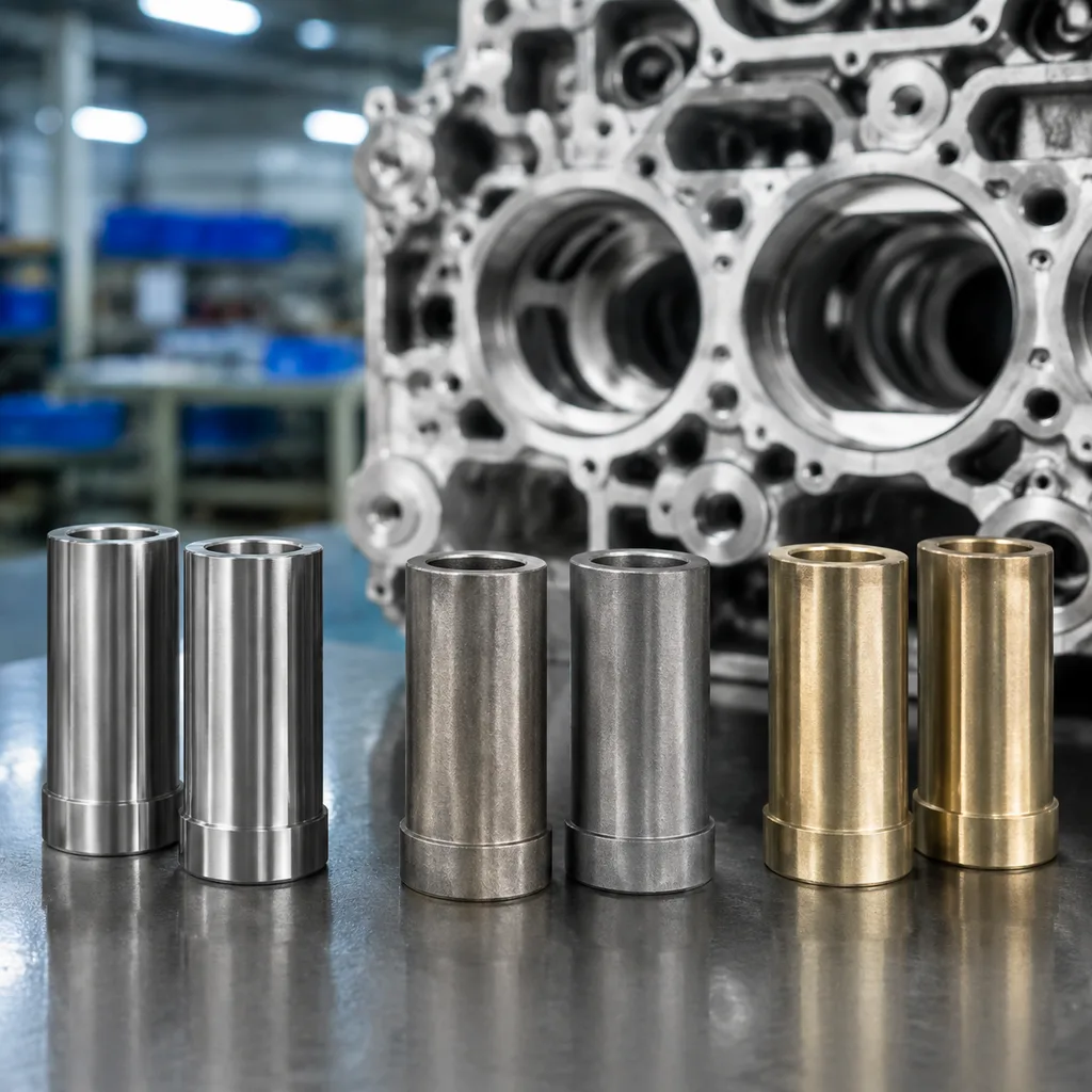
Comparison: material choice versus dimensional stability
Material is not just a cost line. It changes wear behaviour, heat transfer, machinability and how stable the finished bore remains under load. Avoid vague RFQs that ask for “bronze” or “cast material” without a grade, hardness range or performance target.
Common options:
Grey cast iron: good machinability and cost control for many passenger car applications; works where lubrication, stem material and stem coating are conventional.
Sintered iron alloy: controlled porosity and repeatable composition; useful for high-volume programmes that need consistent oil retention and wear behaviour.
Manganese bronze: strong thermal conductivity and seizure resistance; often selected for performance, heavy-duty or hotter exhaust positions.
Phosphor bronze: good wear and corrosion resistance; needs controlled machining and deburring to protect bore finish.
Powder metal with additives: can be engineered for oil retention, hardness and thermal performance when programme volume supports tooling.
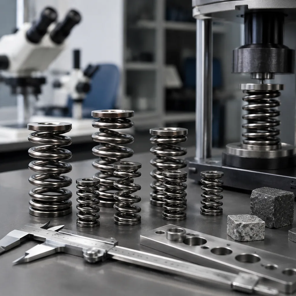
Hardness and microstructure deserve the same attention as alloy name. A guide that machines easily but lacks hardness may pass incoming inspection and still wear quickly. A guide that is too hard, poorly lubricated or finished with the wrong texture can move the wear problem to the valve stem. RFQs should define hardness range, material certificate requirements, heat treatment if used, and whether destructive checks such as microstructure review are required per lot.
The commercial pattern is predictable. Cast iron and sintered iron guides are usually faster to source for catalogue demand because tooling is mature and cycle times are stable. Bronze guides cost more, but they can reduce field risk in hotter or higher-load applications. Make that trade-off explicit instead of leaving it to supplier interpretation.
Driventus manufactures valve guides alongside related engine components and aligns production control with IATF 16949:2016 and ISO 9001:2015 through its documented quality system. Material declarations can also support buyer compliance work under REACH (EC) No 1907/2006 where applicable.
For planning, suppliers commonly quote sample or bridge lots at a higher unit price, then reduce piece price once repeat quantity is confirmed. Typical bands are under 500 pieces for sample/bridge demand, 1,000–5,000 pieces for standard catalogue production, and higher MOQs for custom programmes needing new tooling, gauging or packaging. Lead time follows the same logic: stock or repeat production can ship in 1–3 weeks, standard make-to-order in 3–6 weeks, and new-engineered parts in 6–12 weeks depending on tooling approval and inspection sign-off.
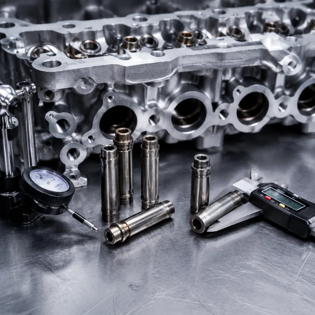
Step-by-step inspection: prove the guide in its installed state
Inspection should mirror how the part is used. A plug gauge in a loose guide is not enough when the bore is expected to change after pressing.
Recommended sequence:
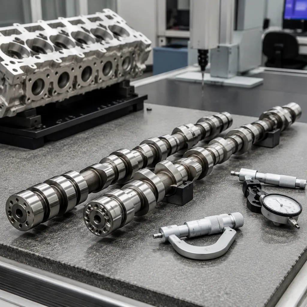
1. Confirm drawing revision and cross-reference. Check application, buyer number, controlled OE-style reference if supplied, material callout and supersession history. 2. Measure OD at multiple heights. Use a calibrated micrometer, bore gauge fixture or air gauge to detect taper, barrel shape and out-of-round. 3. Measure ID before installation. Record bore size, roundness, taper and machining marks before pressing. 4. Check length and chamfers. Confirm lead-in geometry, seal land position, shoulder features and orientation if the guide is asymmetric. 5. Press into a representative head bore. Use the specified interference, head material, installation temperature and lubrication condition. 6. Measure final ID and clearance. Compare the installed bore against valve stem diameter and operating clearance requirement. 7. Verify concentricity to the seat machining datum. This matters when guides are replaced before valve seat cutting or refacing.
Use calibrated measurement systems under ISO 9001:2015 procedures, and keep the method consistent from sampling through release. For higher-volume or safety-relevant supply, request Cp and Cpk on OD, ID and length. A practical recurring target is often Cpk ≥1.33 on critical dimensions, with tighter gates for exhaust-side, turbocharged or emission-sensitive applications.
Ask the supplier to disclose the manufacturing sequence in the quote: raw material receipt, blank forming, sintering or casting, rough machining, heat treatment if used, finish machining, washing, gauging, corrosion protection, packaging and lot release. The order matters. A supplier that reams before final heat treat may hold nominal ID in-house and lose it after the thermal cycle.
For pilot lots, request first-article dimensional data from at least 5–10 pieces per cavity or machine setup. For production, require lot traceability that ties every carton to the run number and inspection record.
Failure modes: where small dimension errors become warranty claims
Valve guide failures rarely announce themselves as a bad guide. The field symptom may be oil burning, noise, poor compression, misfire or intermittent valve sticking. That is why purchasing controls need to connect dimensions to failure modes.
Dimensional issue
Likely field symptom
Sourcing control
OD too small
Guide movement, oil leakage, seat misalignment
Define press-fit range and head bore data
OD too large
Cracked head boss, high insertion force or distorted guide bore
Validate insertion force and final installed ID
ID too tight
Valve sticking, high stem wear, misfire or compression loss
Measure after installation, not only before
ID too loose
Oil consumption, exhaust smoke, valve noise and unstable heat transfer
Define finished clearance and bore finish
Poor concentricity
Uneven seat contact, low compression and accelerated seat wear
Control OD/ID runout and seat datum relationship
Incorrect length
Seal interference, reduced support or port obstruction
Confirm installed height, spring clearance and port geometry
</tr></thead><tbody> </tbody></table>For distributors and repair chains, these defects can become warranty cost even when the part looked acceptable on a bench check. A useful PPAP-style package should include dimensional reports, material certificates, process flow, control plan, packaging specification and traceability method. IATF 16949:2016 does not mean a specific part is approved by a vehicle manufacturer, but it does provide a recognised framework for automotive process control, corrective action and production consistency.
The buying decision should compare total landed risk, not only unit price. Include scrap exposure, claim rate, rework labour and special tooling for post-install sizing. A slightly higher-priced guide with stable installed ID, known final clearance and reliable packaging can be cheaper than a low-cost guide that drives repeat head removal.
Buyer Q-and-A: what to send for a quote
A strong RFQ removes assumptions before sampling starts. It should make clear which dimensions are nominal, which are post-installation requirements, and which commercial constraints affect the quote.
Include the following where available:
Application data, engine code and target market.
Drawing with nominal valve guide dimensions and full tolerance stack.
Valve stem diameter, material, coating and surface finish.
Cylinder head material and finished guide bore diameter.
Required interference fit and installation process.
As-supplied ID and required final ID after fitting.
Material grade, hardness range and bore surface roughness.
Annual volume, forecast by month or quarter, batch size, packaging and labelling requirements.
Target MOQ, expected price breaks at sample, pilot and production quantities, and any tooling amortization assumptions.
Lead-time expectations for first article, repeat production and emergency replenishment.
Inspection report format, sampling level and capability requirements.
Compliance requirements, including REACH (EC) No 1907/2006 where applicable.
For pricing, separate the part price from one-time charges. Ask suppliers to quote unit price, tooling or gauging cost, packaging cost, and any premium for tighter tolerance, special certification or 100% bore inspection. If the programme is forecast-driven, request at least three price bands so the commercial team can compare landed cost before award. A common pattern is a higher first-lot price below 1,000 pieces, a lower steady-state price at 1,000–5,000 pieces, and another reduction above that when longer runs improve material yield and machine utilisation.
If a buyer is consolidating pistons, gaskets, water pumps and valve train components, align dimensional reporting formats across the engine category. Driventus can review samples, drawings and cross-reference lists for aftermarket distributors, OEM/Tier-1 sourcing teams and multi-location repair chains. For current valve guide availability and adjacent engine parts, see our catalog, or request a quote with the drawing and target annual volume.
Frequently asked questions
Both are common. Semi-finished bores are often preferred for repair operations because pressing the guide into the head can reduce or distort the ID. Final reaming or honing after installation gives better control of valve stem clearance. For sourcing, ask the supplier to state the as-supplied bore size, the recommended final sizing method and the expected installed ID after correction.
Outside diameter, inside diameter after installation, concentricity, length and seal land position are usually the highest-risk dimensions. OD controls retention, while final ID controls valve stem clearance, oil control and valve stability. In commercial terms, the best controls are the dimensions that tie directly to fit, first-pass yield and warranty exposure, not only the dimensions easiest to measure.
Yes. Driventus can quote from drawings, samples or controlled cross-reference data for aftermarket and OEM/Tier-1 programmes. Driventus is an independent aftermarket manufacturer; brand names are referenced for fitment only. Buyers should include annual volume, target MOQ, packaging standard and lead-time requirement with the drawing to get an actionable commercial quote.
For valve guide samples, dimensional reports or programme pricing, send the drawing, material requirement and forecast volume. Contact Driventus at /contact.html