Valve Cover Gasket Symptoms of Failure: Diagnosis Guide
Oil on the top of an engine is evidence, not a verdict. A wet valve cover area can come from a hardened gasket, but it can also come from a loose cover, warped flange, blocked crankcase ventilation system, damaged spark plug tube seal, cracked plastic cover, leaking cam sensor, or fasteners tightened outside the service specification.
This guide focuses on valve cover gasket symptoms of failure and, more importantly, how to prove the source before ordering parts. For procurement teams, distributors, and repair networks, the decision is bigger than “the engine leaks.” The sealing system must match the cover geometry, clamp load, rubber compound, oil exposure, heat range, tube-seal design, packaging condition, MOQ plan, lead time, and documentation requirements for the application.
Driventus is an independent aftermarket manufacturer; brand names are referenced for fitment only.
Read the pattern first: which symptoms actually point to the gasket?
A failed valve cover gasket rarely announces itself with one clean sign. It leaves a pattern. Read that pattern before removing parts.
Common valve cover gasket symptoms of failure include:
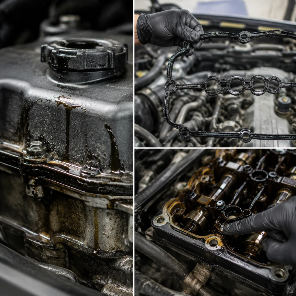
Oil mist, staining, or wetness around the valve cover perimeter, often first visible at corners, cam cap transitions, or the rear edge
Burnt-oil smell after hot running, especially when oil reaches the exhaust manifold, turbo area, downpipe, catalytic converter shield, or heat shield
Oil in spark plug wells or on ignition coil boots
Intermittent misfire after rain, engine-bay washdown, or high humidity when oil and moisture reduce ignition insulation resistance
Fresh oil staining after recent valve cover, PCV, ignition coil, or spark plug service
Light smoke when oil contacts a hot surface
The most useful clues are usually perimeter wetness, burnt-oil smell, and oil in plug wells. Each points to a different risk.
Perimeter wetness often means the gasket has taken a compression set, hardened, cracked, shifted in the groove, or lost contact pressure because the cover or bolt load is uneven. Many modern valve cover fasteners are low-torque fasteners; typical values are often in the 6–12 N·m range, although the vehicle service manual is always the authority. A few extra newton-metres can distort a plastic cover, crush grommets, or squeeze the gasket bead out of place.
Oil in spark plug wells is different. It commonly points to failed spark plug tube seals, distortion around the tube openings, or an integrated seal that no longer holds its shape. Do not assume the outer perimeter gasket is the only failed component. Remove the coils, wick out pooled oil, clean the wells, run the engine to operating temperature, and recheck after 10–20 minutes plus a short road test. If oil returns from the tube land rather than dripping from above, the tube seal or cover geometry is suspect.
Crankcase pressure can also turn a small seep into a heavy leak. A restricted PCV system can push oil past an otherwise marginal seal. Before blaming the gasket alone, inspect the PCV valve, hoses, oil separator, and related passages. Look for collapsed hoses, sludge, poor one-way valve operation where applicable, abnormal idle vacuum behaviour, and excessive pulsing or pressure at the oil filler cap. A valve cover gasket should seal the designed joint. It should not be asked to compensate for abnormal crankcase pressure.
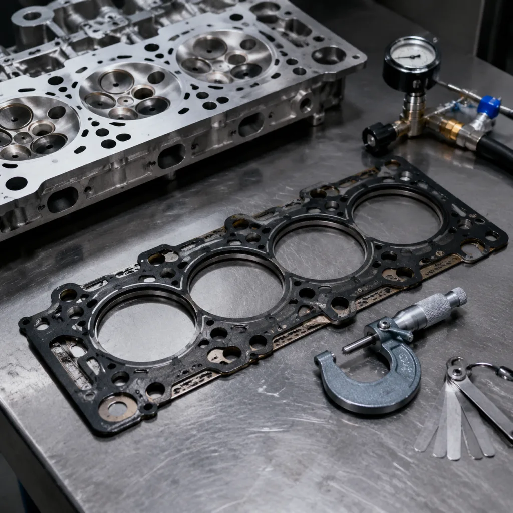
Failure-mode comparison: symptom, false lead, and confirmation point
Check cover flatness, bolt bosses, groove fit, tube seal seating, and torque pattern
Replace the cover if distorted; use the correct profile, new grommets where specified, and the correct sequence
Oil trail at the rear of the engine
Leak travelling along the cover edge, casting, wiring loom, bracket, or bellhousing ledge
Rear main seal
Inspect from the highest wet point downward
Clean and recheck with dye, talc, or controlled run time before condemning another seal
</tr></thead><tbody> </tbody></table>The visible drip is often not the source. Oil can run along castings, harnesses, brackets, splash shields, and bellhousing ledges before it drops. A cover may look dry from above while leaking at the rear edge. A wet plug well may come from a failed tube seal while the perimeter gasket is still serviceable.
Use one confirmation method across the workshop or repair network. Clean the area. Photograph the starting condition. Run the engine to full operating temperature. Inspect with a mirror and lamp. Road test. Recheck. If several oil sources are possible, use UV dye at the dye supplier’s recommended dosage for the oil capacity. Do not overdose it. Talc or developer spray can also show a fresh oil path clearly on a clean, dry surface.
The decision point is the first fresh wet source, not the biggest old stain.
A step-by-step inspection sequence that prevents wrong-part replacement
Start cold. Clean first. Diagnose second.
Degrease the valve cover, cylinder head edge, ignition well area, adjacent brackets, heat shields, and any surface that could carry oil away from the source. Once dry, run the engine to operating temperature and inspect the perimeter with strong lighting. If the path is still unclear, use UV dye, talc, or staged inspection after a short road test.
A practical inspection flow:
1. Record the engine code, production date range, cover type, and previous repair history. 2. Clean suspected leak areas, including plug wells, cover edges, brackets, shields, and nearby sensors. 3. Run the engine until the thermostat opens or the cooling fans cycle. 4. Inspect for the first fresh oil trace, especially at corners, cam cap transitions, rear edges, and tube seals. 5. Perform a 5–10 km road test where safe, including idle and light-load operation, then recheck. 6. If needed, add UV dye according to the dye manufacturer’s oil-volume recommendation and inspect with a UV lamp. 7. Remove ignition coils only after the outer area is clean so dirt and oil do not fall into the plug wells. 8. During disassembly, check cover flatness, groove condition, bolt bosses, grommets, and tube-seal seating before assuming a gasket-only repair will hold.
Quick inspection checklist
Confirm the leak starts at the valve cover, not above it from a cam sensor, oil pressure switch, filler cap, PCV hose, oil separator connection, VVT solenoid seal, or related plug
Check the cover for cracks, warpage, damaged bolt bosses, stripped inserts, heat whitening, and distortion around plug-tube openings
Inspect the gasket for hardening, flattening, splits, swelling, glazing, missing sections, or areas that moved out of the groove
Check spark plug wells for pooled oil and inspect coil boots for swelling, softening, carbon tracking, oil saturation, or arcing marks
Verify crankcase ventilation is not blocked, kinked, frozen, sludge-restricted, or incorrectly routed after prior service
Confirm fasteners were tightened in the correct sequence and to the service manual value, not tightened until the leak appeared to stop
Look for old sealant residue, incorrect RTV placement, excess RTV, or debris trapped between the gasket and cover groove
Inspect mating surfaces for scratches, corrosion, tool damage, leftover gasket material, and dents from prying
For dimensional checks, use a straightedge and feeler gauge on accessible cover lands after removal. Many workshops treat visible plastic cover distortion, cracked bolt bosses, or a flange gap that cannot be corrected by normal clamp load as a cover replacement condition. For aluminium covers, inspect bent flanges near pry points and local damage around corners. For plastic covers, pay close attention to heat-aged areas near exhaust runners and turbochargers.
Do not condemn a rear main seal, timing cover, or oil pan just because oil is visible at the back or bottom of the engine. Separate the leak source from the oil path. That one discipline reduces unnecessary part replacement and comeback risk.
Decision point: gasket-only repair, seal set, or complete cover?
Replacement is the right decision when the gasket has lost resilience. Extra sealant will not restore it. More torque will not restore it either. In many cases, over-tightening makes the next leak more likely by distorting the cover, damaging bolt bosses, crushing isolators, or forcing the gasket out of position.
Replace the gasket assembly when you find:
Visible cracking, splits, swelling, glazing, hardening, or missing rubber sections
Persistent seepage after cleaning and torque verification to service data
Oil inside spark plug wells, under ignition modules, or around plug-tube seals
Warped aluminium flange or distorted plastic cover flange
Grommets, isolators, or tube seals that no longer hold shape or rebound after removal
A gasket that no longer sits securely in the groove during dry fitment
Evidence that the previous leak was caused by incorrect sealant, wrong gasket profile, trapped rubber, or the wrong tightening sequence
Then decide how much to replace.
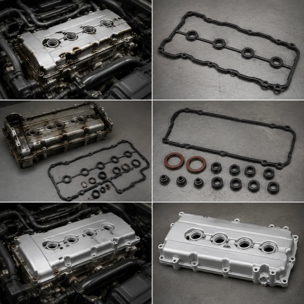
A gasket-only repair can be appropriate when the cover is flat, the groove is clean, tube seals are serviceable or separately replaced, bolt grommets are in specification, and the PCV system is functioning normally. A full seal set is usually the better choice where perimeter seals and plug-tube seals age together. A complete cover assembly may be the safer option when the cover includes non-serviceable tube seals, an integrated PCV diaphragm, oil separator features, cracked plastic, damaged bosses, or heat distortion.
Use the service manual for the tightening pattern and torque value. Good installation practice is simple but unforgiving: start all fasteners by hand, seat the cover evenly, tighten in the specified centre-out or criss-cross sequence, and use a calibrated low-range torque wrench. Where RTV is specified at cam cap corners, half-moon areas, or timing cover transitions, apply only the bead size and location specified by service data. A common field range is a small 2–4 mm bead at local joints, but the vehicle procedure is the authority.
After installation, run the engine to operating temperature, allow a short heat soak, and recheck the perimeter and plug wells. A second inspection after one duty cycle or customer drive is useful for fleets and repair chains. Do not perform a post-installation “extra tightening” unless the service procedure requires it. Uncontrolled retightening can create the next failure.
Buyer spec deep-dive: what separates a reliable gasket from a lookalike
For B2B sourcing, a valve cover gasket is not just a rubber profile in a bag. It must fit the cover groove, sealing land, bolt-load strategy, plug-tube design, oil chemistry, temperature range, packaging route, and application record.
Start with the material. Common valve cover gasket compounds include NBR, ACM, FKM, and silicone-based materials. Selection depends on oil exposure, heat range, cover design, compression requirements, and OEM-style sealing needs. A colour match is not a specification. Ask for the material family, target hardness, ageing performance, oil resistance, and compression-set behaviour.
Practical acceptance checks often include:
Shore A hardness control
Critical-profile dimensional inspection
Compression set testing
Oil ageing performance
Heat ageing performance
Corner and bead moulding consistency
Flash control at sealing areas
Fitment checks against the actual cover groove and application record
For moulded rubber gaskets, critical cross-section and bead heights may be controlled in tenths of a millimetre. Overall length can carry wider tolerance because rubber is flexible, but the sealing bead cannot be casual. The bead must compress evenly without rolling, twisting, falling out of the groove, or losing contact after heat cycling.
Key procurement checks:
Dimensional match to cover groove, bolt centres, corner radii, locating tabs, and plug-tube openings
Material specification with target hardness, heat range, oil resistance, and ageing performance
Stable sealing force after heat cycling, oil exposure, and storage
Consistent moulding at corners, joints, beads, parting lines, and integrated tube seals
Clean flash control so the gasket seats fully without trimming or installation stress
Correct elasticity for the application, not only correct appearance
Packaging that protects the profile from twisting, compression, UV exposure, and deformation in transit
Batch or lot traceability for warranty analysis and quality follow-up
Fitment confirmation by engine code, production date, market, and cover revision where applicable
Compliance documentation for IATF 16949:2016, ISO 9001:2015, and REACH (EC) No 1907/2006 where required
For MOQ, price, and lead-time planning, separate catalogue supply from new-development or modified-tooling work. Stocked aftermarket references may be available in mixed cartons or modest distributor MOQs. Private-label packaging, material validation, and custom tooling normally require higher MOQ because compounding, mould setup, inspection, and packaging artwork are fixed-cost steps.
Unit price usually moves with four variables: annual volume, material grade, cavity count/tooling efficiency, and packaging requirement. A bulk-packed NBR gasket will not price like an ACM or FKM set with tube seals, bolt grommets, barcode labels, and retail cartons.
A usable RFQ should state the OE/reference number, engine code, annual forecast, first order quantity, packaging format, required documents, destination, and whether samples are for fitment only or full validation. If tooling or formulation changes are involved, allow time for drawing confirmation, mould trial, dimensional report, material test report, packaging approval, and pre-shipment inspection.
For distributors, fleet programs, and repair-chain supply, repeatability matters as much as first-fit appearance. A gasket that looks correct but has poor compression recovery, weak corner moulding, or deformed packaging can increase installation time and warranty exposure. Driventus supports distributor, OEM, and repair-chain programs with documented inspection and traceability. Review our catalog, check the quality system, or ask about custom manufacturing. For adjacent engine sealing and powertrain items, see engine components.
Frequently asked questions
Yes. If oil reaches spark plug wells or coil boots, ignition energy can leak to ground and the engine may misfire. Confirm the leak source first, then inspect the coils, boots, plug tubes, and ignition insulation before replacing ignition parts.
No. Use sealant only where the service information specifies it, such as corner joints, half-moon areas, or cover transitions. Excess sealant can squeeze into the engine, block oil return passages, or prevent the gasket from seating correctly.
Check the cover profile, material specification, batch traceability, packaging protection, dimensional consistency, and validation records. For fleet, distributor, or repair-chain supply, confirm fitment by application record before committing to repeat orders. RFQs should also include annual forecast, first order quantity, packaging type, document requirements, and target delivery window.
If you need fitment confirmation, sample supply, or bulk pricing, use our contact page: /contact.html