Turbo actuator dimensions are a key control point when sourcing replacement or OE-equivalent electronic and pneumatic actuators. A small mismatch in lever arm length, mounting hole position, connector orientation, or rod travel can stop calibration, trigger boost deviation, or create warehouse-level rework. For procurement teams, the dimensional drawing should be reviewed alongside thermal durability, corrosion resistance, electrical characteristics, and end-of-line calibration records. This guide outlines the actuator dimensions typically requested by aftermarket distributors, OEM/Tier-1 sourcing engineers, and repair-chain category managers when qualifying turbo actuator supply. It also explains how Driventus controls drawings, gauges, and inspection records under IATF 16949:2016 and ISO 9001:2015. Driventus is an independent aftermarket manufacturer; brand names are referenced for fitment only.
Core dimensions to define before sourcing
A turbo actuator cannot be specified by motor type, pressure range, or boost-control function alone. The housing, bracket, output lever, rod interface, and connector must fit the turbocharger assembly envelope and match the movement geometry required by the vane or wastegate mechanism. Buyers should request a controlled 2D drawing or 3D model with datum references, tolerance zones, revision status, and the measurement method for each critical feature.
Dimension item
Typical procurement check
Why it matters
Mounting hole centre distance
±0.10–0.20 mm depending on bracket design
Prevents bracket stress, bolt misalignment, and distorted installation
Lever arm length
±0.10 mm on calibrated arms
Sets the movement ratio for the vane ring or wastegate flap
Rod end or clevis width
±0.05–0.15 mm
Controls free play, side loading, and assembly fit
Stroke or travel range
Application-specific, usually verified at EOL
Confirms the actuator can cover the required boost-control range
Connector clocking angle
Drawing-controlled
Avoids harness interference and latch-access issues
Housing height and envelope
Maximum boundary check
Prevents contact with heat shields, compressor covers, and brackets
Shaft diameter and flat position
Gauge-controlled
Maintains lever indexing and repeatable output position
</tr></thead><tbody> </tbody></table>The drawing should state whether dimensions are measured before calibration, after calibration, or after thermal cycling. This distinction is important because electronic actuators may learn or store a calibrated position after assembly. In many applications, the final calibrated position is more relevant to vehicle performance than free-state rod length, while the free-state dimension still matters for safe installation and linkage engagement.
Mechanical tolerances and materials
Mechanical tolerance strategy should follow the actuator’s function. Brackets and covers need repeatable fitment, but lever geometry, shaft indexing, and output position require tighter control because they influence the turbocharger air path. A part that bolts on correctly can still fail functional verification if the lever angle, stroke window, or rod interface sits outside the calibrated range.
Typical specification points include:
Bracket material: zinc-plated steel, stainless steel, or heat-resistant alloy selected for engine-bay temperature, corrosion exposure, and stiffness.
Housing material: aluminium alloy or high-temperature polymer chosen for dimensional stability, vibration resistance, and heat ageing performance.
Output shaft: hardened steel or treated alloy steel with controlled surface finish on bearing and sealing areas.
Fasteners: zinc-nickel or equivalent corrosion-protection system where salt spray resistance is required.
Seals and boots: fluorocarbon or silicone-based materials for applications with continuous high-temperature exposure.
Surface treatment: coating thickness, adhesion, and corrosion performance verified against the customer drawing or agreed specification.
For B2B supply, dimensional capability should be supported by Cpk or Ppk records on critical-to-function characteristics. Buyers should not rely on a general sample measurement report unless it identifies datums, gauge type, sample size, measurement temperature, and inspection frequency. A practical incoming inspection plan often checks five to ten pieces per shipment for mounting geometry, lever indexing, rod interface, and connector orientation, while the manufacturer retains full functional testing and end-of-line calibration data for traceability.
Electronic actuator interface dimensions
Electronic turbo actuators introduce dimensional risks that may not appear on simple pneumatic units. The connector shell, pin position, gasket compression, cover height, and latch clearance can cause installation or signal issues even when the bracket pattern is correct. For this reason, turbo actuator dimensions should be reviewed as a mechanical and electrical interface package rather than as isolated housing measurements.
Important interface checks include connector keyway position, terminal depth, latch clearance, cable harness approach angle, gasket seating face, seal compression height, and cover-to-bracket clearance. If a harness cannot latch cleanly or a connector seal is crushed unevenly, the root cause may be dimensional variance rather than an electrical defect.
Electrical and environmental validation should be reviewed with the drawing package. Driventus uses process controls aligned with IATF 16949:2016 and ISO 9001:2015, and buyers can review our quality system before supplier nomination. Material declarations may also be required for markets applying REACH (EC) No 1907/2006 and RoHS Directive 2011/65/EU, depending on the customer’s compliance scope.
For emissions-related applications, calibrated actuator movement influences boost pressure, exhaust temperature, and engine operating conditions. Vehicle-level compliance is governed by regulations such as ECE R-83 or US EPA requirements, but component suppliers should not claim vehicle approval unless formally authorised. Driventus does not claim approval, endorsement, or sponsorship by any vehicle manufacturer.
How to compare drawings across suppliers
When comparing turbo actuator dimensions from different suppliers, the biggest risk is treating nominal values as equivalent without checking tolerances, datums, and calibration logic. A nominal 42.0 mm lever arm can behave differently if one drawing references the shaft centreline and another references a stamped lever edge. The same issue applies to connector angle, rod length, shaft flats, and housing envelope dimensions.
Buyers should request the following documents with the quotation package:
1. Controlled 2D drawing with revision number and datum scheme. 2. Critical characteristics list with inspection frequency and acceptance criteria. 3. Initial sample inspection report, preferably with at least five measured samples. 4. Functional test curve or end-of-line calibration printout. 5. Material and surface-treatment specification. 6. Packaging drawing showing protection for lever, rod, connector, and sealing areas.
A sourcing comparison should also cover service-life validation. Useful tests may include thermal cycling, vibration, salt spray, connector retention, seal ageing, and repeated actuation under load. The relevant test method may be customer-specific, so buyers should not assume that a published standard covers every actuator performance requirement. Where a new bracket, lever, rod end, or connector orientation is required, Driventus can support custom manufacturing based on drawings, samples, or validated benchmark parts.
Specification checklist for RFQ packages
A clear RFQ reduces sampling loops, improves supplier comparison, and avoids late-stage disputes over fitment. For distributors and import managers, the strongest purchase specification combines part identification, turbo actuator dimensions, validation evidence, inspection rules, packaging protection, and commercial controls.
RFQ field
Recommended detail
Application reference
Engine code, turbo family, actuator type, and market region where available
Part reference
Buyer’s internal number or generic OE cross-reference only, if supplied
Drawing requirement
2D PDF plus CAD file when available, with revision control
Critical dimensions
Mounting centres, lever length, stroke, rod interface, connector orientation, and envelope
Tolerance requirement
Drawing tolerance, agreed inspection standard, or critical-characteristic list
Validation
EOL calibration, thermal cycling, vibration, connector retention, and corrosion checks
Compliance
IATF 16949:2016, ISO 9001:2015, REACH, and RoHS where applicable
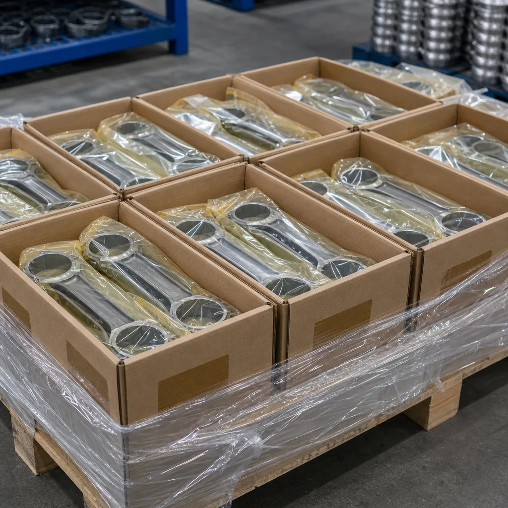
Packaging
Connector protection, lever protection, sealing-surface protection, and export carton specification
Lot traceability
Batch code, inspection report, production date, and calibration record reference
</tr></thead><tbody> </tbody></table>Driventus can supply actuator samples for dimensional review, trial assembly, and functional verification. Procurement teams can review our catalog for related engine and powertrain components, or request a quote with drawings, annual demand, target price, and inspection requirements. For regulated markets, compliance documents should be agreed before purchase order release rather than requested after shipment.
Frequently asked questions
Mounting hole centres, lever arm length, stroke range, connector orientation, rod interface, and housing envelope are usually the most critical. For electronic units, calibrated end positions and connector fit are also important because they affect installation, signal integrity, and boost control.
Yes. Driventus can review 2D drawings, CAD files, samples, benchmark parts, and validation requirements for custom manufacturing. Critical dimensions, materials, tolerances, gauges, and inspection methods should be agreed before tooling or sample production.
No. Driventus is an independent aftermarket manufacturer; brand names are referenced for fitment only. We can provide dimensional, material, process, traceability, and functional validation records for buyer review.
If your team is comparing turbo actuator drawings or qualifying a new supply source, send the part data, target volume and inspection requirements for review at /contact.html