Turbo actuator dimensions are a critical sourcing checkpoint, but they do not confirm fitment on their own. Buyers still need to verify mounting pattern, shaft travel, connector type, rod length, control range, and calibration values against the target turbocharger and vehicle application. For aftermarket, OEM replacement, and contract manufacturing programmes, the practical objective is dimensional consistency, stable actuation response, and repeatable performance under heat, vibration, and boost cycling. Driventus is an independent aftermarket manufacturer; brand names are referenced for fitment only. We build turbo-related components in Taizhou, Zhejiang, with production systems aligned to IATF 16949:2016 and ISO 9001:2015. The sections below focus on what actually separates a safe match from a near miss: the dimensions to capture, the failure modes they prevent, the tolerances that matter, and the procurement details needed to issue a clear RFQ. If you are matching a known OE reference, record the OE number, sample part, drawing revision, and actuator type before comparing dimensions.
What to measure first, and why
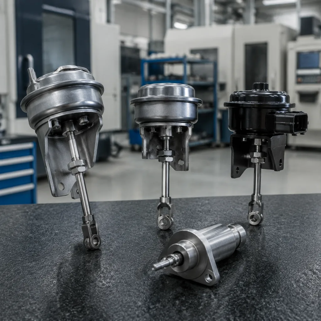
For sourcing, start with the dimensions that decide whether the actuator can physically install and move correctly. Measure the actuator as a complete assembly and as a functional subassembly.
The minimum data set should include:
Overall housing length, width, and height
Mounting flange thickness and bolt-hole centre distance
Rod length at nominal position and full stroke
Connector orientation and terminal style
Bracket offset, arm length, and clevis geometry
Vacuum port or electrical interface diameter
Body clocking angle relative to the bracket
Thread size, pitch, and effective engagement length
The reason to begin here is simple: a part can look right and still fail on the bench. A 1-2 mm change in bracket offset can shift rod alignment enough to create preload on the wastegate lever. The same risk appears on electronic actuators, where harness clearance and heat shielding can fail even when the outer envelope matches. For replacement work, record the full dimensional stack, not just housing size. A unit with a 68 mm housing length, 42 mm width, 31 mm height, 14 mm rod eye offset, and 26 mm nominal rod length may still be wrong if the clevis is clocked 15° off or the connector body sits 6 mm higher than the OE part. Capture at least one calibrated measurement from each critical face and confirm the datum scheme used by the supplier; edge-to-edge readings on curved housings are often misleading.
Where parts fail when dimensions are close but not correct
This is the decision point many buyers miss: a turbo actuator can be close enough to quote, yet still wrong for service. The most common failure modes are dimensional, but they show up as installation or calibration problems.
Typical mismatch patterns include:
Rod travel that misses the lever stop
Mounting pitch that forces bracket stress
Connector orientation that clashes with the harness
Clevis clocking that prevents preload adjustment
Body height that interferes with shields or pipes
Pin diameter that introduces play or binding
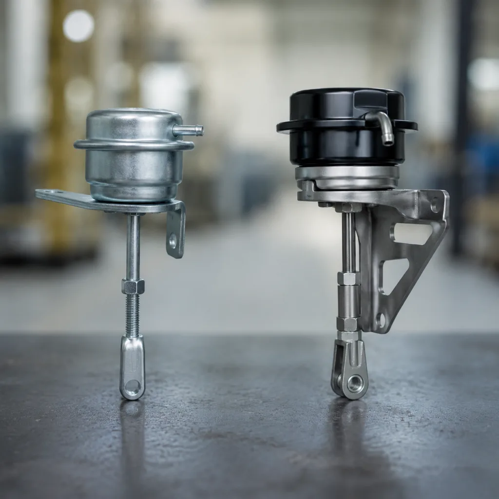
These are not cosmetic issues. If rod travel is 2 mm short, the actuator may never reach the commanded position. If the mounting pitch is off by a small amount, the installer may pull the bracket into place and create long-term stress in the housing or fasteners. On electronic units, a connector that appears equivalent can still fail because the keying, sealing depth, or terminal orientation is different. For pneumatic units, a mismatch in lever geometry often shows up only after the part is pressurised: the rod moves, but not in the correct arc. The practical lesson is to compare the complete stack-up, then check how that stack-up behaves under load, not just on paper.
Specification ranges buyers usually see
Turbo actuator dimensions vary by turbo family and control method, but procurement teams often see these working ranges:
Parameter
Common range
Procurement note
Housing length
45-95 mm
Check space to heat shield and compressor cover
Housing width
35-80 mm
Confirm clamp or bracket clearance
Housing height
28-75 mm
Verify bonnet and pipe proximity
Rod travel
5-25 mm
Match wastegate or VGT lever requirement
Mounting hole pitch
20-60 mm
Measure centre-to-centre, not edge-to-edge
Clevis pin diameter
4-10 mm
Match lever and wear bushing specification
Thread size
M4-M8
Confirm pitch, not only nominal diameter
Connector seal OD
8-16 mm
Check ingress protection and harness routing
</tr></thead><tbody> </tbody></table>These ranges are directional, not universal. Electronic VGT units usually need tighter positional control than pneumatic wastegate actuators, especially where response calibration depends on shaft travel and spring preload. A typical pneumatic canister may have 6-12 mm of useful rod movement with spring preload set in the 30-120 N band, while an electronic actuator may require positional repeatability within 0.2-0.5 mm over the calibrated stroke window. For export programmes, ask for drawings in millimetres and confirm revision control on the drawing pack. If the application is high-risk or low-volume, request both the 2D drawing and a control plan that states the measured characteristics, sample size, and acceptance criteria used at final inspection.
Tolerance controls that matter in production
Dimensions only help if the supplier can hold them through machining, assembly, and heat cycling. For fit-critical features, the drawing should say what is critical to fit and what is cosmetic.
Key controls include:
Bracket flatness and hole position
Rod straightness and thread engagement
Diaphragm or actuator body seal integrity
Fastener torque retention after thermal cycling
Corrosion resistance on exposed steel parts
Connector retention force and terminal lock integrity
A practical target is ±0.10 mm to ±0.30 mm on machined interfaces, with wider tolerances on non-functional outer shells. In procurement terms, hole centre distance may be held to ±0.15 mm, bracket flatness to 0.20 mm max, rod straightness to 0.10 mm per 100 mm, and clevis pin bore position to ±0.20 mm where the part is load-bearing. Where the part may contact hot-side components, surface finish and coating thickness should be documented with the dimensions because plating build-up can affect clearance. A zinc or phosphate coating should be specified with its target thickness range, because a 5-12 μm coating can change the assembly gap enough to affect clip engagement on tight brackets. For high-volume programmes, ask for Cp/Cpk evidence or at least a first-article report showing the mean and spread of the critical dimensions, not just a pass/fail sample.
Step-by-step fitment check before you buy
A short, disciplined check prevents most avoidable mismatch claims.
1. Match the turbo family and application code. 2. Confirm OE reference and supersession history. 3. Compare the complete dimension set, not only the part number. 4. Check rod travel against the wastegate or VGT lever stop. 5. Review connector type, polarity, and sealing method. 6. Confirm bracket clocking and installation angle. 7. Ask for sample validation on the target turbocharger if the project is high volume. 8. Record the measured installed preload or baseline position before releasing the PO. 9. Verify that the actuator reaches both end stops without binding across the full thermal window.
For sensitive applications, request production samples and compare them against the customer’s master part before launch. Electronic units should be bench-checked for movement range, repeatability, return-to-home behaviour, and current draw at the calibrated end stops. A good incoming sample should repeat within about 0.3 mm on positional return and stay within the supplier’s declared operating voltage or signal range. Pneumatic units should be checked for leak rate and spring response under the intended pressure window; a practical purchasing check is to test at the specified control pressure plus and minus 10% to see whether the rod still begins moving smoothly and returns without hesitation. If the part will be used on a fleet or warranty-sensitive programme, ask the supplier to document the test jig, the fixtures used to hold the turbo, and the exact measurement reference point.
Comparison: standard stock part or custom build?
The fastest way to avoid over-specifying the wrong part is to decide whether the application is a clean replacement or a geometry problem. If the turbo actuator is obsolete, if the lever geometry has changed, or if the application needs a different connector or bracket offset, custom manufacturing is usually the better route.
Use custom tooling when:
The OE part is unavailable or superseded
The actuator must fit a non-standard turbo housing
The customer needs a private-label spec with controlled dimensions
The programme requires regional packaging or labelling changes
The customer needs a specific rod length, preload, or connector clocking that is not available off the shelf
For standard replacement items, buyers should prioritise dimension match, lead time, and repeatability. For custom projects, the process should start with the sample or drawing, then move to critical-to-fit dimensions, supplier feasibility, a pre-production sample, and finally a volume PO tied to the agreed inspection standard. Custom tooling can add a one-time NRE or tooling charge, while repeat pieces should be priced separately after tooling approval. If you need factory-level clarification, the quality system page outlines the controls behind production release. For standard replacement sourcing, review our catalog and the broader engine components range to align actuator sourcing with adjacent turbo and sealing parts. Driventus also supports custom manufacturing for defined dimensional targets.
What to request in an RFQ packet
Procurement teams should not ask for a price alone. The RFQ should force the supplier to prove the part can be built, measured, and shipped consistently.
Useful commercial documents include:
Dimensional drawing with revision number
PPAP-style sample record, where required
Material and surface treatment declaration
Packaging specification for transit protection
Lot traceability and inspection report
Country-of-destination compliance statement
Test summary with measured travel, preload, and leak or current-draw results
That file should reference the applicable quality framework and any chemical compliance statement for the destination market. Driventus operates with an IATF 16949:2016 and ISO 9001:2015 quality system, and export documentation can be aligned to REACH (EC) No 1907/2006 where material reporting is required. Buyers comparing suppliers should also state annual volume, target annual usage, forecast split by part number, packaging unit, and the requested delivery window. Those inputs drive price and lead-time accuracy. If the supplier is quoting a standard actuator, ask for MOQ by part number and packaging configuration; common commercial structures are 100-500 pieces per SKU for stock items and 300-1,000 pieces for customised configurations with unique tooling or labels. Ask for tiered quotations at 100, 500, and 1,000-piece levels, plus an ex-works sample price and freight assumption. Lead time should be separated into sample lead time, mass-production lead time, and repeat order lead time.
FAQ: quick answers for buyers
What should I measure first on a turbo actuator?
Start with overall envelope, mounting pitch, rod length, and connector orientation. Those four values usually determine whether the part can physically install before any calibration work begins. After that, confirm rod travel, clevis size, and the bracket clocking angle, because those details often decide whether the actuator can be adjusted into the correct preload window.
Are identical dimensions enough to confirm replacement fit?
No. The part also needs the correct travel range, lever geometry, preload, control type, and calibration curve. Two actuators can share the same envelope and still fail in service if the rod stroke is 2 mm short, the pin diameter is wrong, or the connector keying is different. Buyers should treat dimensions as a gate, not a full approval.
Can Driventus make a custom version to match my sample?
Yes. We can build to a verified sample or drawing when the existing part is obsolete, modified, or requires a different bracket or connector layout. For a clean quotation, send the sample, the OE reference if available, the target annual volume, the required tolerance band, and any packaging or label rules so we can confirm the tooling and lead time.
Frequently asked questions
Start with overall envelope, mounting pitch, rod length, and connector orientation. Those four values usually determine whether the part can physically install before any calibration work begins. After that, confirm rod travel, clevis size, and the bracket clocking angle, because those details often decide whether the actuator can be adjusted into the correct preload window.
No. The part also needs the correct travel range, lever geometry, preload, control type, and calibration curve. Two actuators can share the same envelope and still fail in service if the rod stroke is 2 mm short, the pin diameter is wrong, or the connector keying is different. Buyers should treat dimensions as a gate, not a full approval.
Yes. We can build to a verified sample or drawing when the existing part is obsolete, modified, or requires a different bracket or connector layout. For a clean quotation, send the sample, the OE reference if available, the target annual volume, the required tolerance band, and any packaging or label rules so we can confirm the tooling and lead time.
If you need a drawing check, sample comparison, MOQ guidance, price tiers, or a project quotation, please use our request a quote page at /contact.html.