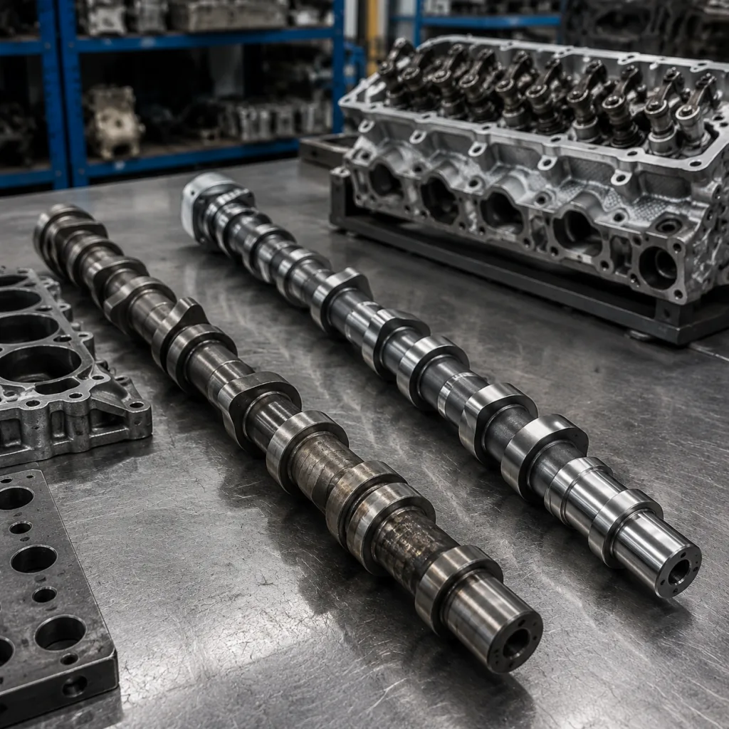
Camshaft for Citroën Berlingo Replacement: Buyer Guide
A camshaft for Citroën Berlingo replacement has to match more than the headline fit. Journal dimensions, timing phasing, end-float, trigger geometry, lift, and finish all need to line up if you want a durable repair instead of a short-lived fix. For buyers, the real job is to confirm OE function under load, at temperature, and over the expected service interval, then lock those values into a controlled drawing or approved sample. Driventus is an independent aftermarket manufacturer; brand names are referenced for fitment only. We supply camshafts and related engine components through controlled production in Taizhou, Zhejiang, with quality management aligned to IATF 16949:2016 and ISO 9001:2015. This article focuses on the decisions that matter most when sourcing a replacement: fitment validation, common failure modes, comparison points between supply routes, and the checks to complete before release.
Decision points: what must match first
A replacement camshaft is not acceptable just because it fits the cylinder head. Start with the items that determine whether the engine will run correctly and survive in service:
- Correct engine code and valve-train layout: SOHC or DOHC, lobe count, and trigger-wheel position
- Journal diameter, overall length, and thrust-face geometry
- Valve lift, duration, lobe separation, and lobe indexing
- Compatibility with hydraulic lifters, rocker followers, or bucket tappets
- Surface hardness and finish for wear resistance
- Oil-feed hole location, if applicable, and chamfer orientation on thrust and journal edges
- Sensor target tooth count and missing-tooth pattern, where cam-position feedback is used
For fleet repair and distributor stock, the safest route is OE-equivalent geometry backed by a matched inspection report. If a catalogue lists OE 06A107065 or another reference, use it only as a fitment cross-check. Do not treat it as proof of application. The same Berlingo badge can cover different valve-train packages across markets, so always confirm engine code, emission level, and model-year break before buying.
Failure modes: where replacements go wrong
Most sourcing failures happen after the purchase order is already in motion. The part looks right, but the engine complains immediately: noise, misfire, poor idle quality, or fast wear. The usual causes are predictable:
- Cam phasing is off, so valve events no longer line up with the intended timing window
- Journal stack-up creates excess clearance, oil starvation, or seizure risk
- End-float is outside the assembly window, which can shift timing under load
- Lobe geometry differs from the approved sample, changing lift and airflow
- Trigger geometry or tooth count is wrong, breaking sensor signal integrity
- Surface finish is too rough, which accelerates scuffing during break-in
- Hardness is inconsistent, which shortens wear life and can damage followers
If a supplier cannot show measurement evidence, assume the risk is real. A camshaft problem often appears as a vehicle symptom, but the root cause is usually hidden in the dimensions. That is why buyers should ask for first-article data, sample approval records, and a clear control plan before volume release.
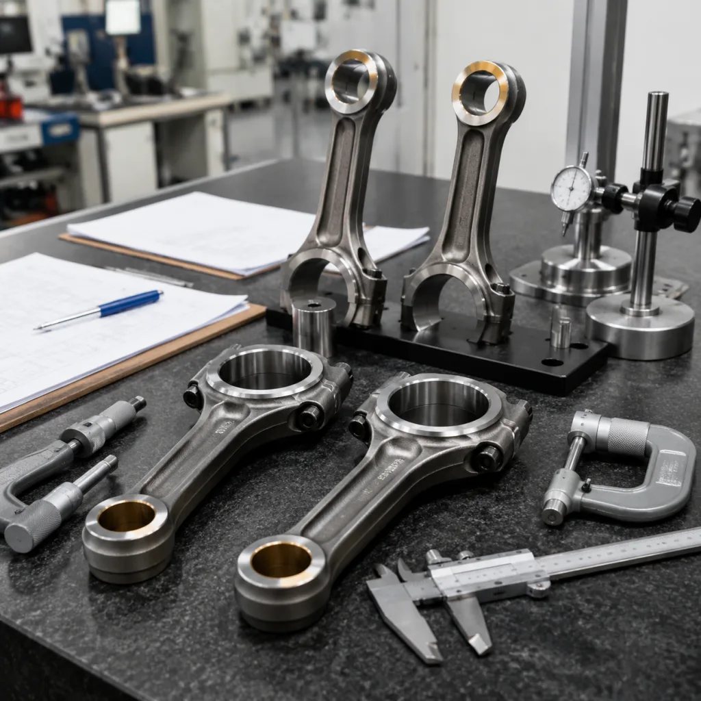
How to verify dimensional match
Use the approved drawing or master sample as the baseline, then compare the candidate part against it. The goal is not general similarity. The goal is repeatable dimensional control.
| Check point | What to verify | Practical tolerance target | Why it matters | |
|---|---|---|---|---|
| Journal diameter | Match to OE drawing and head bore clearance | Typically within ±0.01 mm to ±0.02 mm of the approved drawing | Prevents seizure, oil starvation, or excess clearance | |
| Overall length | End-to-end dimension and thrust-face position | Commonly within ±0.10 mm, or tighter if the OE sample demands it | Avoids thrust-load errors and timing drift | |
| Lobe lift | Compare against OE lift spec at each lobe | Usually within ±0.05 mm on finished lift, subject to engine family | Protects valve timing, airflow, and idle quality | |
| Base-circle diameter | Verify against the approved master sample | Typically within ±0.03 mm to ±0.05 mm | Keeps valve lash and valve events consistent | |
| Lobe indexing | Confirm trigger and lobe orientation | Zero ambiguity allowed; use master-angle or digital angle data | Avoids incorrect injection or ignition timing | |
| Surface finish | Measure Ra on lobes and journals | Commonly Ra 0.2–0.4 μm on lobes and journals after finishing | Reduces break-in wear and scuffing | |
| Hardness | Verify case or through-hardening spec | Usually HRC 50–60 on wear surfaces, depending on material route | Extends wear resistance and fatigue life | |
| Straightness/runout | Check between centers after finish grinding | Often ≤0.03 mm TIR, or per drawing | Prevents vibration and premature bearing wear | |
| End-float | Confirm thrust clearance in assembly | Must sit within OE assembly window, often 0.05–0.20 mm | Ensures correct axial control in service |
| Route | Best for | Buyer priority | MOQ / price / lead-time logic | Typical risk |
|---|---|---|---|---|
| OE-equivalent replacement | Workshop supply, distributor stock | Fast fit, stable dimensions | Lower tooling cost, usually lower MOQ, and shorter lead time once the drawing is approved; unit price is driven mainly by material grade, grinding time, and heat-treatment route | Low if validation is complete |
| Custom manufacturing | Discontinued engines, engineering changes | Exact control of geometry and metallurgy | Higher setup cost, usually higher MOQ, and a longer sample-to-release cycle; unit price falls as annual volume rises and inspection scope stabilises | Higher if input data is incomplete |