A thermostat stuck thermostat complaint rarely stays as a single workshop problem. One vehicle overheats, another never reaches normal temperature, and a third returns with coolant residue around a new housing. For repair chains, importers, and aftermarket distributors, the real cost is not the thermostat itself. It is the repeat repair, the disputed warranty claim, and the loss of confidence in a fast-moving SKU.
The part is small, but its job is exact. An engine thermostat controls coolant flow between the engine, radiator, bypass circuit, and heater system. In many light-vehicle applications, initial opening is commonly specified around 82–92°C. Full opening often follows about 10–15°C later, with valve stroke in the 7–10 mm range depending on design. Those numbers affect emissions strategy, fuel consumption, cabin heat, gasket load, turbocharger temperature, EGR cooler protection, and water-pump behaviour.
That is why buyers cannot treat thermostat sourcing as a catalogue-fitment exercise. Outer diameter and gasket shape are only the beginning. Opening temperature, stroke, bypass function, sealing geometry, housing material, calibration repeatability, packaging, and batch traceability all decide whether the part works in the field.
This article approaches the issue as a procurement and technical decision file: how to read symptoms, avoid false failure conclusions, understand common sticking mechanisms, define specifications, validate stock, and manage supplier risk. Driventus is an independent aftermarket manufacturer; brand names and OE-style references are used only to identify fitment and do not imply endorsement or approval.
Start With the Failure Pattern, Not the Part Number
A thermostat does not fail in only one way. It can stay closed, stay open, drag through its travel, leak through a seal, or distort inside an integrated housing. Each pattern points to a different risk for the buyer.
Failure mode
What the vehicle usually does
What buyers risk if the case is misread
Stuck closed
Engine overheats quickly from cold, often within 5–15 minutes. Radiator inlet remains much cooler than the engine outlet. Coolant may boil, vent, or push through the cap or expansion tank.
Workshops may replace water pumps, radiators, coolant sensors, or even suspect head gaskets before confirming coolant flow.
Stuck open
Warm-up is slow. Coolant temperature stays below the intended control range. Cabin heat is weak. Fuel use may rise and emissions readiness can be affected.
A replacement line may be blamed for “poor heater performance” or “engine too cold” even when the supplied calibration is wrong for the application.
Partially open or slow-moving
Temperature moves up and down under load. Fan cycling becomes frequent. Heater output changes. Overheating may appear only on hills, in traffic, or at highway speed.
Intermittent behaviour creates repeat visits and unclear warranty reports. A batch concern may be missed because each case looks different.
Seal or housing leak
Coolant level drops. Dried coolant appears around the housing. Air enters after cooling. A 1.0–1.5 bar pressure check shows loss.
Claims may be assigned to the thermostat element when the cause is housing flatness, bolt torque, O-ring compression, dirty mating surfaces, or wrong seal installation.
</tr></thead><tbody> </tbody></table>For a distributor or repair network, a thermostat stuck thermostat complaint should be logged with more than “overheats” or “runs cold.” Minimum useful data includes ambient temperature, time from cold start to 80°C, peak temperature under load, scan-tool coolant temperature, fan command, radiator inlet and outlet readings, heater performance, coolant concentration, pressure-test result, vehicle mileage, and installation date.
Visual inspection alone is weak evidence. A thermostat can look clean and still open late because the wax element has aged, the spring force has changed, the guide has contamination, or the valve binds after thermal expansion. The opposite is also true: a dirty thermostat may not be the root cause if the radiator is blocked, the water-pump impeller is slipping, the pressure cap is weak, the sensor is inaccurate, the electric fan is not following ECU command, or air remains trapped in the system.
Good warranty screening starts by separating three questions: Is the thermostat moving correctly? Is the cooling system able to transfer heat? Was the correct application and installation procedure used? Only then does the part number become the central issue.
A Seven-Step Check Before Approving or Rejecting a Claim
Use the same diagnostic path every time. It reduces false claims against replacement stock and gives procurement teams comparable evidence across workshops, regions, and batches.
1. Verify coolant level and concentration. Low coolant, trapped air, oil contamination, or the wrong antifreeze mix can imitate thermostat failure. Check the expansion tank, pressure cap, visible leaks, and coolant strength with a refractometer or approved tester. Where the vehicle maker specifies it, a common working range is about 45–55% glycol by volume. Too much water lowers boiling protection. Too much glycol can reduce heat transfer.
2. Remove air from the equation. Air around the wax element slows heat transfer and can create sudden temperature spikes. Follow the vehicle bleeding procedure: heater setting, bleed screws, vacuum filling, scan-tool activation, or electric pump command where required. For high-volume workshops, vacuum filling to roughly -0.8 to -0.9 bar before refill can reduce claims on difficult cooling layouts.
3. Compare sensor data with physical temperatures. Read coolant temperature through the scan tool and compare it with infrared readings at the thermostat housing, engine outlet, radiator inlet, and radiator outlet where access allows. If the ECU shows 105°C while the thermostat outlet or radiator inlet remains near 40–50°C after warm-up, investigate closed thermostat, air lock, or no-flow conditions before condemning the radiator.
4. Watch the hose temperature change. On many systems, the upper radiator hose stays relatively cool until the thermostat opens, then rises quickly within 1–3 minutes as flow begins. A hose that warms gradually from cold may indicate leakage past the valve or a thermostat stuck open. Be careful with mapped, electronically heated, or complex bypass systems; their behaviour can differ from older mechanical layouts.
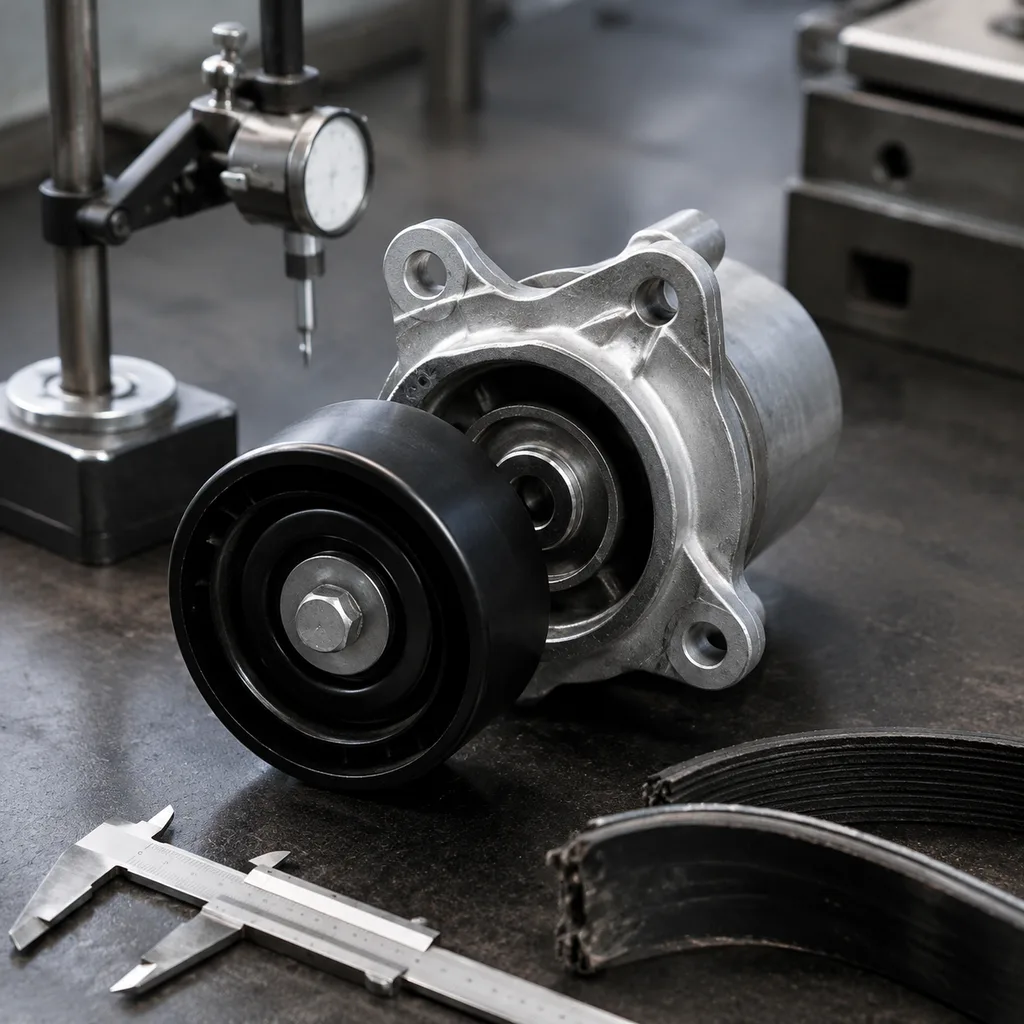
5. Check the rest of the heat-rejection system. A thermostat cannot compensate for a blocked radiator core, damaged pump impeller, restricted passage, collapsed hose, weak pressure cap, or fan-control fault. Pressure-test the cap and cooling system to the application rating, commonly around 1.0–1.5 bar, and verify fan activation against ECU command rather than dashboard gauge position only.
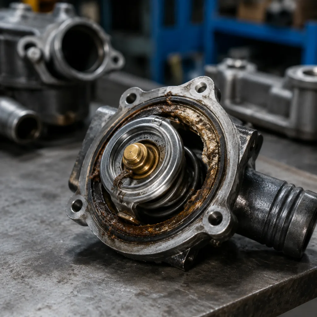
6. Inspect the removed component like evidence. Look for torn seals, corrosion deposits, sealant contamination, wax leakage, broken bridge arms, distorted plastic housings, damaged locating tabs, reversed installation, incorrect gasket position, or witness marks from forced assembly. Record housing flatness, bolt-hole damage, connector condition, and RTV bead thickness if sealant was used.
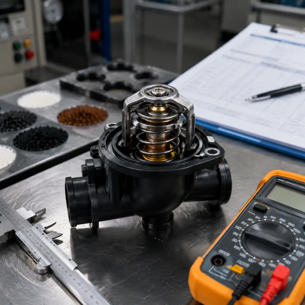
7. Bench-test only when the result will change the decision. Heat the thermostat in water and record first movement, rated opening point, full-stroke temperature, maximum stroke, and return movement during cooling. Use a calibrated thermometer, suspend the thermostat away from the pan base, agitate the water, and raise temperature slowly—about 1–2°C per minute near the rated point. Never apply flame directly to the component.
If several vehicles using the same SKU report similar behaviour, isolate samples by batch and workshop. Record application, engine code, mileage, coolant type, installation date, production mark, and symptom details before returning parts for supplier review. This separates genuine production drift from wrong application selection, air-bleeding errors, coolant contamination, and workshop handling damage.
Why a Thermostat Sticks: The Mechanisms Buyers Should Care About
A mechanical thermostat is a calibrated thermal valve. Most use a wax pellet that expands at a defined temperature and drives a piston against spring force. Newer assemblies may combine the thermostat with a plastic housing, bypass disc, sensor, heater, connector, or electronic control function. Different architecture, same buyer concern: movement must start at the right temperature, reach the required stroke, seal when closed, and repeat after heat cycling.
The common failure mechanisms are practical, not mysterious:
Coolant contamination. Rust, gasket debris, oil, hard-water scale, excessive RTV, and silicate drop-out can jam the guide, coat the seat, or reduce valve travel. Fine deposits are enough to delay opening by several degrees.
Wax-element leakage or fatigue. If wax fill is lost or the capsule ages, movement becomes late, weak, or incomplete. An 88°C thermostat that first moves at 96–100°C in a controlled bench test is not acceptable simply because it eventually opens.
Spring fatigue or corrosion. Spring force controls the opening and closing balance. Corrosion on the spring, bridge, or guide increases friction and may create partial sticking only when the part is hot.
Wrong calibration for the engine. Physical fit does not prove correct function. A 75°C unit used where the engine strategy expects 87–92°C can cause overcooling, poor fuel economy, weak heater performance, or emissions complaints.
Housing distortion. Plastic or aluminium housings can warp because of heat, overtightening, poor moulding control, or corrosion. Plastic flange flatness outside roughly 0.10–0.30 mm, depending on gasket design, can cause leaks even if the valve element is sound.
Air pockets after service. Air around the wax capsule insulates it from coolant temperature. The gauge may climb quickly while the thermostat responds late.
Burrs, flash, rough guides, or weak alignment control. Stamped edges, moulding flash, unstable crimping, or misaligned bridges can add friction. Some parts pass a room-temperature hand check and bind only after expansion.
Installation error. Wrong orientation, missing jiggle-pin alignment, reused flattened seals, excessive sealant, or uneven torque can restrict movement or cause leaks. Small M6 housing bolts are often specified around 8–12 N·m, but the vehicle procedure always controls the final value.
The sourcing lesson is clear: a thermostat is not defined by shape alone. Buyers need control of opening temperature, full stroke, bypass disc height, jiggle-pin orientation, seal compression, housing interface, material behaviour, and hot-state movement. A close-looking catalogue match can still generate field returns if any of those details drift.
Specification Deep-Dive: What to Put in the Sourcing File
A useful thermostat sourcing file reads like a functional specification, not a price worksheet. Catalogue cross-references may include generic OE-style references, such as OE 06A… where application data supports them, but brand-owned numbers should not be presented as approvals, authorisations, or endorsements.
Include these items before approving volume supply:
Opening temperature in °C, with tolerance by application. A typical aftermarket control target is rated temperature ±2°C to ±3°C for initial opening unless the drawing requires a different window.
Full-open stroke and full-open temperature. Ask for actual values, not “OK.” Many designs require about 7.0–10.0 mm stroke at rated temperature plus 10–15°C, but the drawing and application decide.
Critical dimensions. Main valve diameter, bypass valve diameter, flange thickness, locating features, O-ring groove, bolt holes, and housing interfaces should be controlled by drawing. Functional machined or moulded interfaces may require tolerances around ±0.05–0.15 mm; non-critical outer features can be wider.
Seal material. Coolant-resistant EPDM is common where suitable, often peroxide-cured, with hardness around 60–75 Shore A and compression-set data after heat ageing.
Wax element and calibration controls. Ask how the supplier controls wax mass, capsule crimp height, piston protrusion, wax fill process, and post-assembly thermal calibration.
Housing material. Identify PA66-GF30/35, aluminium alloy, brass, stainless steel, or other specified materials. Plastic housings should state glass-fibre content and heat-ageing limits. Metal housings should state corrosion protection.
Leak-test method. Integrated housings, cover plates, sensor ports, and seals should have a defined test. Production checks often use air pressure around 1.0–1.5 bar for 10–30 seconds with a clear pressure-drop or bubble-leak limit.
Corrosion-resistance evidence. For metal elements, request salt-spray or coolant-immersion results where relevant. Targets may range from 96 to 240 hours depending on exposure and material.
Thermal ageing and cycling data. The useful report shows before/after opening temperature, stroke change, leakage, and visual condition. A pass/fail line is not enough for program approval.
Packaging protection. The carton must prevent bent bridges, crushed seals, cracked housings, damaged connectors, displaced O-rings, and broken bleed pins during sea freight and warehouse handling.
Traceability. Batch code, cavity number, production date, inspection record, and packaging label should link part number, quantity, production lot, inspection lot, and carton number.
Driventus manufactures thermostat assemblies and related engine cooling components under a documented quality system. Our inspection approach is aligned with IATF 16949:2016 and ISO 9001:2015 process-control expectations, including incoming material checks, in-process dimensional inspection, final sampling, functional checks, and batch traceability. Environmental and material compliance requirements can also be reviewed against REACH (EC) No 1907/2006 where applicable to the destination market.
Validation Plan: Tests That Catch Problems Before the Market Does
Some thermostat defects do not appear on day one. Slow movement, partial sticking, seal compression loss, and plastic-housing distortion often show up after heat cycles. A reliable supply program therefore checks initial conformity and ageing behaviour.
Test area
What it proves
Evidence to request
Opening temperature test
Wax element, spring, and valve calibration
Temperature curve, first movement point, full-open point, test medium, and equipment record. Target often rated temperature ±2–3°C.
Stroke measurement
Coolant flow capacity at operating temperature
Stroke value at the specified test temperature and measurement method; 7–10 mm is a common design range where applicable.
Return or closing test
Ability to close after cooling and avoid overcooling
Closing temperature range, return movement, and repeatability after at least 3–5 heat/cool cycles.
Leak test
Closed-valve sealing or integrated-housing sealing
Pressure, duration, allowable leakage, and sample size; production screening often uses 1.0–1.5 bar air for 10–30 seconds.
Thermal cycling
Stability after expansion and contraction
Cycle count, before/after opening data, stroke change, leakage, and visual condition. 500–1,000 cycles is a useful benchmark for program approval.
Dimensional inspection
Fit to housing, gasket, bypass, and mounting interfaces
Drawing report covering critical dimensions, flange thickness, O-ring groove, bolt holes, bypass disc height, and connector features where present.
Material verification
Correct polymer, rubber, wax capsule, and metal grades
Material certificates, internal verification records, hardness data, supplier declarations, or resin/rubber traceability.
Packaging and transport check
Protection against bent bridges, damaged seals, and cracked housings
Drop or vibration test summary, packing method, carton specification, and sea-freight palletisation method.
</tr></thead><tbody> </tbody></table>Incoming inspection does not need to repeat the full validation plan. It does need to catch obvious batch and handling risk. For importers and wholesalers, a practical first-shipment plan is to inspect 5–13 pieces per lot for visual and dimensional items, then bench-test 3–5 pieces for opening temperature and stroke. Repeat the functional check after a supplier process change, tooling change, material change, or unexplained market complaint.
For plastic housings or integrated thermostat modules, add checks for moulding flash, thread quality, flange flatness, connector damage, sensor-port sealing, and O-ring retention. These issues often become “thermostat stuck” complaints even when the thermal valve is not the failed feature.
Repair chains should also standardise installation guidance. Clean the mating face. Use new seals where specified. Avoid excessive sealant. Torque bolts evenly. Bleed air correctly. Use coolant that matches the vehicle requirement. These controls protect the supplier relationship because they prevent installation faults from being recorded as product defects.
Buyer Scenario: Building a Thermostat Program That Does Not Become a Warranty Program
Imagine two suppliers offer the same fast-moving thermostat SKU. Supplier A is cheaper and provides a broad cross-reference list. Supplier B costs slightly more but provides opening-temperature curves, stroke data, housing flatness checks, leak-test limits, batch traceability, and packaging details. If the annual volume is high, the better commercial decision is not obvious from unit price. It depends on warranty rate, technician time, return freight, damaged packaging, customer credits, and how fast root-cause analysis is completed.
A strong thermostat program should be judged on coverage accuracy, batch consistency, packaging protection, and claim response. Buyers should evaluate whether the supplier can support catalogue products, private-label requirements, and application-specific development—not only whether the first quotation is low.
Driventus supplies engine cooling and powertrain components for aftermarket distributors, repair chains, and OEM/Tier-1 related projects. Buyers can review standard lines through our catalog, including relevant engine component families at /products/engine-components.html. For applications requiring a specific housing, opening temperature, connector position, seal geometry, bypass design, or private-label packaging, custom manufacturing can be discussed with drawings, samples, or target vehicle data.
Before placing volume orders, request:
Application list with engine codes, model years, market notes, and supersession history.
Sample approval report with thermal, dimensional, leak, and material test results.
Opening temperature and tolerance for each application, not only for the product family.
Packaging specification for distributor handling, barcode requirements, inner boxes, and export cartons.
Batch marking method and traceability link between production, inspection, and shipment.
Warranty analysis process, including sample return requirements, root-cause report timing, and corrective-action format. A workable SLA is acknowledgement within 2 working days, preliminary findings within 5–7 working days after sample receipt, and 8D/CAPA closure within 20–30 working days for confirmed supplier issues.
Lead time, minimum order quantity, forecast requirements, and options for mixed-container or phased delivery.
Commercial assumptions should be visible before the order is placed. For catalogue thermostat assemblies, trial orders may start around 100–300 pieces per fast-moving SKU or 500–1,000 pieces for private-label packaging. Custom housings, sensors, or new tooling usually require higher MOQs because of mould set-up, validation, and material purchasing. Standard production lead time is commonly 30–45 days after sample approval and deposit; 45–60 days is more realistic for mixed-SKU export orders or first private-label runs.
Price also moves by design. Simple insert thermostats sit at the low end. Integrated plastic housings with seals and sensors cost more. Mapped or electronic thermostats need additional electrical, leak, and thermal validation. Compare landed cost with defect allowance, packaging loss, warranty rate, claim-handling time, and delivery reliability. That is the difference between buying a thermostat and managing a thermostat program.
Driventus is an independent aftermarket manufacturer; brand names are referenced for fitment only. No vehicle manufacturer approval or endorsement is implied by catalogue cross-reference, application listing, or fitment description.
Frequently asked questions
Rapid overheating while the radiator inlet hose remains cool is a common sign. In many cases the engine outlet may exceed 100°C while the radiator inlet is still far cooler. However, coolant level, air pockets, radiator blockage, fan control, water-pump performance, pressure-cap condition, and sensor accuracy should be checked before confirming thermostat failure.
It may not cause immediate overheating, but it can prevent the engine from reaching its intended operating temperature. This can increase fuel use, reduce heater performance, affect emissions control, dilute oil during repeated cold operation, and create customer complaints after service.
Ask for opening temperature and tolerance, full-open stroke, full-open temperature, dimensional reports, seal material and hardness, housing material, leak-test pressure and duration, thermal-cycling evidence, batch traceability, packaging protection details, MOQ, lead time, and confirmation that the manufacturing system follows IATF 16949:2016 and ISO 9001:2015 process-control expectations.
For thermostat samples, application matching, or export quotation details, contact Driventus to discuss fitment data, MOQ, lead time, packaging, and batch requirements. You can [request a quote](/contact.html) or send your sourcing brief through /contact.html