A thermostat housing is small, but when it fails it can take a vehicle out of service through coolant loss, overheating, or poor warm-up control. For distributors and repair chains, replacement needs to be repeatable across engine platforms, not treated as a one-off workshop task. This guide turns thermostat housing how to replace into a B2B decision and execution checklist: when to replace, what to inspect, how the job fails, what materials to specify, and which supplier evidence matters. It is written for sourcing teams, technical managers, and workshop operators who want fewer comebacks and better first-time fit. Driventus supplies thermostat housings and related engine components for aftermarket programmes, with production controls aligned to IATF 16949:2016 and ISO 9001:2015. Driventus is an independent aftermarket manufacturer; brand names are referenced for fitment only.
When Replacement Beats Resealing
Thermostat housing replacement is usually the right call when the housing itself is damaged, not just the seal. Look for leakage around the joint, cracking, stripped fastener bosses, sensor port damage, or repeat overheating after the thermostat has already been checked.
Plastic housings can deform after heat cycling. Aluminium housings can corrode at hose necks or gasket lands if coolant chemistry is off. In both cases, resealing only postpones the fault if the base surface is no longer sound.
Common symptoms and likely housing-related causes:
Symptom
Likely cause
Check
Coolant residue at the joint
O-ring flattening, flange distortion, or gasket compression loss
Pressure test to 15–20 psi (1.0–1.4 bar) and inspect the seam
Overheating under load
Thermostat misalignment, bypass restriction, trapped air, or poor bleed procedure
Compare scan-tool temperature with OE opening range
Slow warm-up
Thermostat stuck open or wrong temperature rating
Confirm opening temperature, often 82–92°C depending on engine
Hose seepage or blow-off
Damaged bead, clamp seating issue, or undersize neck
Inspect neck geometry and hose retention under clamp load
Repeated gasket failure
Warped face, contamination, or excess torque
Check flatness and torque records
Coolant temperature fault code
Sensor-port leak, damaged connector, or wrong sensor depth
Verify scan data and port dimensions
</tr></thead><tbody> </tbody></table>For fleet and chain workshops, document mileage, coolant type, cap pressure, and any earlier cooling-system work. That record helps separate installation error from part failure. As a practical threshold, if the housing cracks, leaks under pressure, or shows flange distortion beyond about 0.10 mm across the sealing land, replacement is usually safer than another seal attempt.
What to Verify Before the Job Starts
Before removal, confirm the part against the vehicle application, engine code, sensor configuration, hose routing, and OE cross-reference where available. Use OE references as fitment cues only, not as a claim of vehicle-maker approval.
Recommended workshop items:
Replacement thermostat housing, plus thermostat if integrated
Correct gasket or O-ring
Fresh coolant to OE specification
Drain pan, hose clamp pliers, and a scraper safe for aluminium or plastic
Calibrated torque wrench in the low-torque range
Cooling-system pressure tester or vacuum-fill tool
Scan tool for temperature and fan checks
Straightedge or feeler gauge for repeat-failure cases
PPE and coolant disposal containers
Pre-work checks should also include hose condition, clamp spring tension, connector lock integrity, and mating-material type: plastic-to-plastic, plastic-to-aluminium, or aluminium-to-aluminium. For B2B programmes, define whether the housing is supplied as a bare casting or as a complete assembly with thermostat, sensor, bleed screw, and gasket.
Packaging matters too. Ask for seal separation, capped hose necks, and damage controls that match your channel. For procurement, request dimensional reports on hose-neck outer diameter, sealing-face flatness, bolt-hole position, and overall height. Our thermostat housing and related engine items are listed in our catalog, including broader engine components for cooling and sealing programmes.
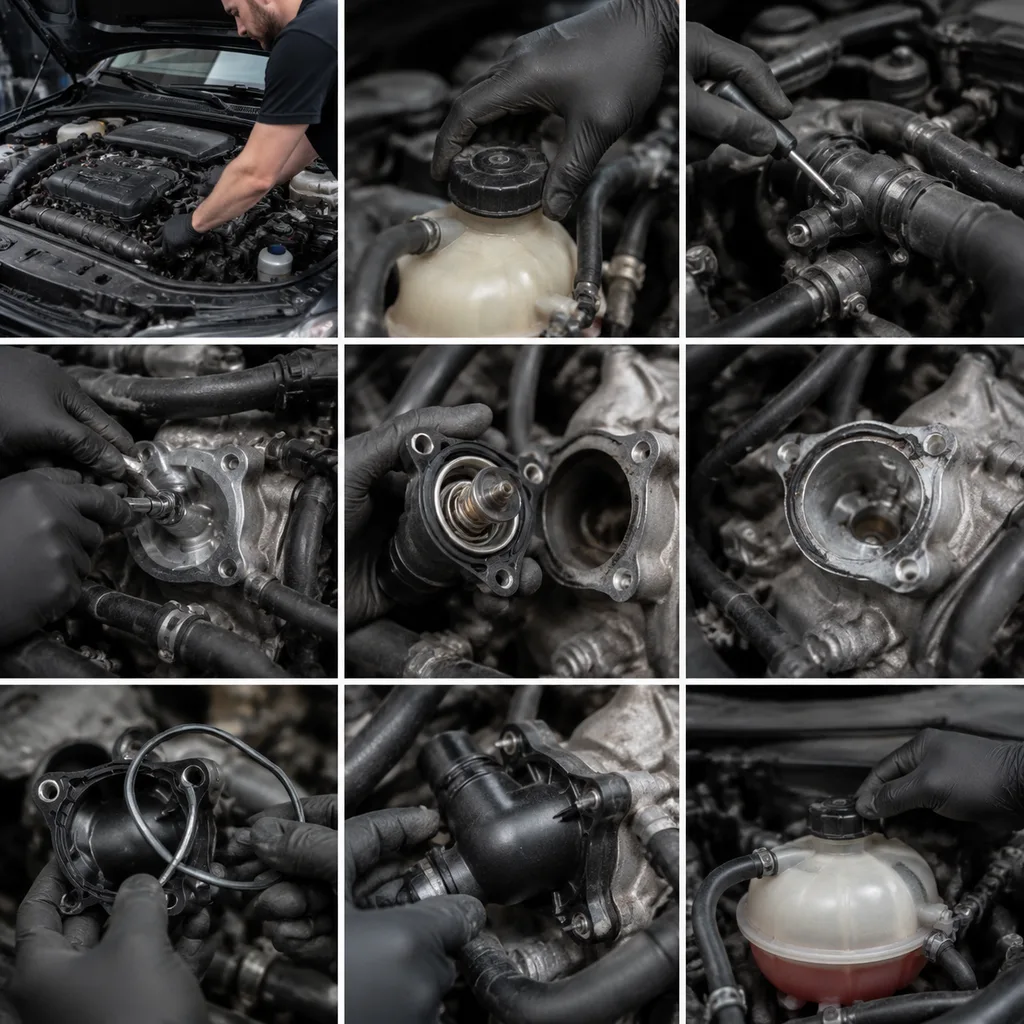
Thermostat Housing How to Replace, Step by Step
The layout changes by engine, but the sequence is consistent. Always follow the vehicle service data for drain method, torque values, and bleeding steps.
1. Let the engine cool fully. Never open a pressurised cooling system. 2. Disconnect the battery where required. This matters near coolant sensors or charged wiring routes. 3. Drain coolant to a controlled level. Lower the level below the housing joint and capture fluid for compliant disposal or reuse only if allowed. 4. Remove access parts. Intake ducts, covers, or brackets often block the housing. Photograph hose and connector routing first if the bay is tight. 5. Disconnect hoses and connectors. Release clamps without cutting into hose necks. Replace hoses that are swollen, cracked, or no longer clamp evenly. 6. Remove fasteners evenly. Do not pry against the sealing face. If bolts vary in length, map their positions before removal. 7. Clean the mating surface. Remove old gasket material without gouging the head, block, or coolant outlet face. 8. Install the new housing and seal. Confirm thermostat orientation, bleed-feature position, and correct O-ring seating. Use sealant only if service data allows it. 9. Tighten in stages. Follow the specified sequence and torque. Over-torque is a common cause of plastic flange distortion and aluminium thread damage. 10. Reconnect hoses, sensors, and brackets. Seat clamps behind the hose bead and confirm full connector engagement. 11. Refill and bleed the system. Vacuum fill if available. Otherwise fill slowly and bleed in the sequence specified by the OEM. 12. Run to operating temperature. Inspect for leaks at idle, during fan cycling, and after cool-down.
This is the practical core of thermostat housing how to replace work: control sealing faces, torque, and air bleeding rather than treating it as a simple remove-and-fit. Build a 20–30 minute post-install check into the job card so the technician can recheck level, witness marks, and leak points after the first heat soak.
How New Installations Fail
Most comeback claims trace to a few repeat failure modes. That is useful, because each one points to a different control gap.
Pinched or twisted seal: Usually caused during seating. The leak appears immediately or after the first heat cycle.
Warped flange: Often linked to over-torque, uneven tightening, or an old housing that was already out of flat.
Air trapped in the circuit: The engine may overheat, run hot at idle, or show unstable heater output even though the part is sound.
Wrong thermostat orientation: Common on assemblies with bleed features or jiggle pins.
Clamp mispositioning: A hose can seep even when the housing is fine.
A clean comeback review should answer three questions: was the part out of spec, was the install procedure wrong, or was the system condition already poor? If the answer is unclear, pressure-test the system before replacing the same part again. That is faster than guessing and cheaper than a second labour event.
For distributors, the lesson is simple: the part, the seal, and the install process behave as one system. A good housing still fails if the mating face is contaminated or the cooling system is not bled correctly.
Material Choices and Spec Checks
The replacement process is strongly affected by housing design. Buyers should evaluate more than the external shape.
Feature
Plastic housing
Aluminium housing
Buyer check
Weight
Lower
Higher
Logistics and application fit
Heat-cycle behaviour
Can creep or warp if resin is poor
Stable, but may corrode
Material grade and coolant compatibility
Hose neck durability
Sensitive to clamp over-force
Stronger necks
Bead geometry and wall thickness
Sealing face
Moulding flatness is critical
Machining quality is critical
Flatness and surface-finish data
Sensor ports
Insert or moulded thread
Machined thread
Thread gauge and leak test
</tr></thead><tbody> </tbody></table>For polymer housings, request resin type, glass-fibre content where applicable, and heat-ageing validation. A common buyer requirement is retained sealing performance after 300–500 thermal cycles between ambient and 110°C coolant exposure, depending on the platform.
For aluminium housings, review casting porosity control, machining capability, corrosion protection, and thread quality. If the housing includes a thermostat, verify opening temperature, stroke, wax-element consistency, and endurance testing. Opening temperature tolerance may need to stay within ±2°C of the specified value, with stroke variation held to the supplier’s declared limit.
Environmental compliance may also matter for EU importers. Suppliers should understand REACH (EC) No 1907/2006 obligations for substances in articles and provide declarations when requested. Cooling-system parts are not brake components, so unrelated claims such as SAE J2527 should not be used as a proxy for acceptance. Ask instead for coolant compatibility against ethylene glycol and the OAT/HOAT formulations used in the target market.
Post-Install Checks That Prevent Comebacks
Post-install verification should be part of the workshop process, especially for multi-site repair chains. A pressure test before road testing can expose seepage without waiting for a customer return.
Minimum checks after installation:
Pressure holds at the specified cap-pressure range, commonly 13–16 psi (0.9–1.1 bar) for many passenger vehicles
No seepage at the flange, hose necks, sensor ports, or bleed screws after a 2–5 minute static hold
Upper and lower hose temperatures rise in a way that matches thermostat opening
Cabin heater output stays stable after bleeding
Fan operation is confirmed by scan tool or controlled warm-up
Coolant level remains stable after one full heat cycle and cool-down
No coolant temperature-related DTCs remain
Torque witness marks stay aligned after the first heat cycle, where recheck policy allows it
For distributors handling warranty claims, ask repair partners for installation photos, pressure-test readings, coolant type, torque confirmation, and final mileage. Those records are usually more useful than a returned part with no vehicle history.
Thermostat housings supplied by Driventus are managed through our documented quality system, with dimensional inspection, sealing-surface checks, assembly verification where relevant, and traceability controls aligned to IATF 16949:2016 and ISO 9001:2015.
Buying and Sourcing Scenarios
A replacement programme works best when the buying spec matches the channel.
For a repair chain, the priority is speed and repeatability. Ask for clear packaging, scan-friendly labelling, stable lead times, and a single installation path for the most common variants. For a distributor, the priority is fitment coverage and low return rate. That means robust cross-reference data, batch traceability, and consistent dimensional control.
A supplier request should include:
Target applications, engine codes, and OE cross-reference format
Annual volume forecast and release pattern
Required configuration: bare housing, complete assembly, sensor included, thermostat included, or gasket kit
Material preference and restricted-substance requirements
Labelling, carton strength, palletisation, and barcode needs
Inspection report format and acceptable quality limits
Target commercial terms: MOQ, sample lead time, production lead time, and buffer stock expectations
A useful buying rule is to separate sample cost from production pricing. Prototype or first-article units may cost more because they include tooling debug, special packing, or hand inspection. Production pricing should be quoted on a volume tier basis with clear breakpoints. Lead time should also be defined by phase: samples in 7–15 days for simple variants, pilot lots in 2–4 weeks, and mass production in 30–45 days once tooling and quality approval are stable.
Driventus supports aftermarket catalogue supply and custom manufacturing for thermostat housings, water outlets, and related powertrain components. The company exports to 60+ countries from Taizhou, Zhejiang, and works with distributors, OEM/Tier-1 buyers, and repair networks that require documented quality controls. For new projects, buyers can request a quote with drawings, samples, or cross-reference lists.
Frequently asked questions
If the thermostat is integrated, replace it as an assembly. If it is separate, many workshops replace it at the same time because the labour overlap is high. Confirm opening temperature and orientation against service data, and check that the supplier’s temperature tolerance is within the engine requirement, often ±2°C.
Common causes include a pinched O-ring, contaminated sealing face, incorrect torque, warped mating surface, damaged hose end, or trapped pressure from poor bleeding. Pressure testing after installation helps identify the source, and a repeat leak often points to installation error or out-of-spec flange flatness rather than the thermostat itself.
Yes. Driventus can review drawings, samples, or fitment lists for aftermarket or OEM/Tier-1 projects. Requirements should include material, ports, thermostat specification, validation plan, packaging, forecast volume, target MOQ, and any required dimensional or leak-test tolerances.
If you are building a thermostat housing programme or need a controlled replacement range for distribution, share your application list, samples, or drawings with Driventus. Contact our team at /contact.html