P0420 Check Engine Light and Engine Valve Diagnosis
A P0420 check engine light does not start at the catalytic converter. It starts with a question: did the catalyst lose oxygen storage capacity, or did the engine feed it the wrong exhaust stream long enough to make the monitor fail?
On most vehicles, P0420 means catalyst system efficiency for Bank 1 is below the ECU’s calibrated threshold. The monitor usually compares upstream and downstream oxygen or air-fuel sensor behaviour during warmed, closed-loop cruise. If the rear sensor begins to follow the front sensor too closely, or calculated oxygen storage drops below the limit, the ECU stores the code.
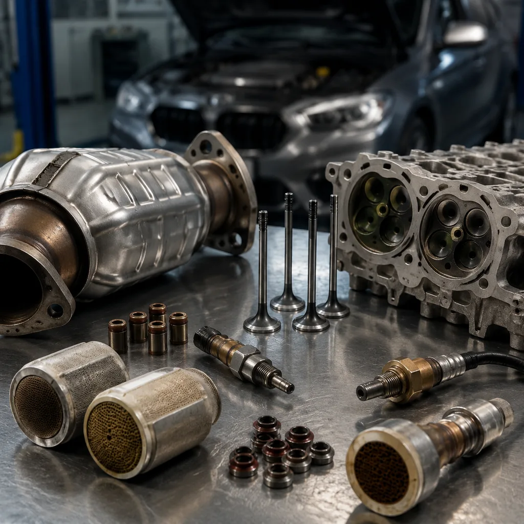
That still does not prove the converter is the root cause. Misfire, oil burning, incorrect fuel control, exhaust leaks and poor valve sealing can all create the same commercial problem: a replacement catalyst that comes back under warranty. Engine valve leakage, burnt exhaust valves, tight lash, worn guides and hardened stem seals can increase hydrocarbon loading, free oxygen, ash deposits and exhaust temperature. A converter exposed to those conditions may overheat, lose efficiency and trigger P0420 even when the replacement part fits correctly.
For repair chains, distributors and sourcing teams, the task is not to label every P0420 as an engine valve problem. It is to separate catalyst failure from sensor, fuel, ignition and mechanical faults before parts are bought in volume. This article gives a practical decision framework for the check engine light p0420 engine valve diagnosis and connects test results with replacement criteria for intake valves, exhaust valves, valve guides, valve stem seals and related engine components. Driventus is an independent aftermarket manufacturer; brand names and OE references, where used, are for fitment identification only.
Decision Point: When a P0420 Code Should Make You Inspect Valves
P0420 is an OBD diagnostic trouble code for catalyst system efficiency below threshold on Bank 1. In many engine management systems, the monitor runs only under controlled conditions: coolant warmed above roughly 70–80°C, stable road speed, light to medium load, closed-loop fuelling and no active misfire or fuel-system DTC. The ECU then compares upstream and downstream oxygen sensor or air-fuel ratio sensor activity. Too much downstream switching, or insufficient calculated oxygen storage, can turn on the check engine light.
The converter is the monitored component. The engine is the supplier of the exhaust stream. That distinction matters.
A leaking exhaust valve can leave oxygen and unburned hydrocarbons in the exhaust. It can also raise exhaust gas temperature and create a weak cylinder contribution that does not always set a hard misfire code. A burnt valve edge, poor seat contact or tight lash may therefore look like a catalyst issue once the catalyst monitor runs. On the intake side, valve wear, guide wear or heavy deposits can disturb cylinder filling and mixture preparation. Hardened valve stem seals or excessive guide clearance can pull oil into the chamber; phosphorus, zinc and calcium ash from oil additives can coat the washcoat and reduce oxygen storage.
Do not order valves from one P0420 event alone. Escalate to mechanical checks when one or more of these triggers appear:
P0420 repeats after converter replacement.
P0420 is logged with misfire history, rough idle or weak cylinder contribution.
Oil consumption is above roughly 0.5–1.0 L per 1,000 km.
Cylinder leakage exceeds the service limit or one cylinder is clearly worse than the rest.
Returned catalysts show melted substrate, overheating marks or grey-white ash.
The same engine family generates repeat catalyst claims across several workshop locations.
For procurement and warranty teams, this is the risk-control line. The code identifies a failed emissions monitor. It does not, by itself, identify the failed part.
Failure-Mode Matrix: Read the P0420 Pattern Before Ordering Parts
P0420 diagnosis improves when technicians stop treating the code as a single fault. The pattern around the code usually tells you where to look first. A matrix also helps multi-location repair groups standardise worksheets and gives distributors a better basis for warranty review. The values below are typical decision aids; the engine service data always has priority.
</tr></thead><tbody> </tbody></table>The matrix is not meant to slow the repair. It prevents the wrong repair. If the evidence points to oil ash, leakage or cylinder imbalance, a converter-only order is a poor bet. If the evidence points to a lazy rear sensor or an exhaust leak, valve replacement is equally wasteful.
For buyers, the same pattern helps define parts demand. A repair programme driven by worn stem seals needs different kit content from one driven by burnt exhaust valves, guide wear or head-seat damage. That distinction should be reflected in the application list, bill of materials and warranty policy when sourcing from our catalog or for a custom programme.
Step-by-Step Triage Before the Converter or Valve Order
Use the scan tool as the starting line, not the finish line. A disciplined sequence catches cheap faults first and reserves cylinder-head work for engines that justify it.
1. Capture the freeze-frame. Record coolant temperature, intake air temperature, vehicle speed, engine load, RPM, closed-loop status, short-term and long-term fuel trim, oxygen sensor or air-fuel ratio sensor data, and misfire counters. P0420 at a 2,000–3,000 rpm steady cruise means something different from P0420 after cold running, repeated misfire or fuel trim beyond ±10%.
2. Clear related faults before judging catalyst efficiency. Misfire, fuel trim, oxygen sensor heater, coolant temperature, mass airflow, manifold pressure, EVAP purge, EGR and cam/crank correlation codes can corrupt the catalyst monitor. Fix them first.
3. Prove the exhaust is sealed. A small leak before or near an oxygen sensor can pull in air and distort rear-sensor readings. Use smoke, pressure decay or ultrasonic leak detection. Pay attention to flanges, flex sections and sensor bosses.
4. Interrogate trims and sensor response. Persistent positive trim can indicate air leaks, injector restriction, inaccurate airflow measurement or valve sealing loss. Negative trim can point to over-fuelling, leaking injectors, excessive fuel pressure or contamination. A zirconia upstream sensor should react quickly to induced rich/lean changes; a slow sensor can make the monitor lie.
5. Check ignition and injector contribution. A weak coil, worn plug or uneven injector can overload the catalyst with unburned fuel and heat. Inspect plug colour and gap, coil dwell, misfire counters, injector balance and fuel pressure retention before condemning the converter.
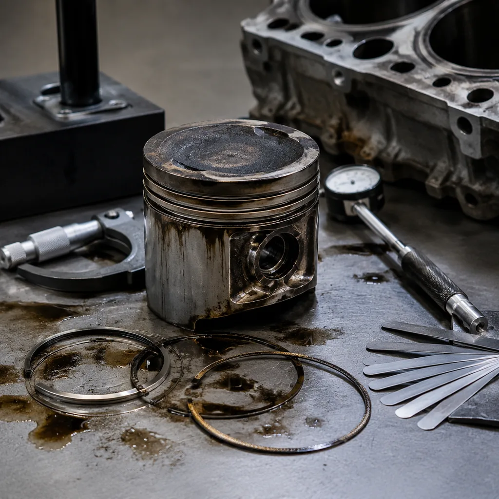
6. Run compression and leak-down tests. Disable fuel and ignition, crank with a charged battery and open throttle where required. Healthy cylinders are commonly within 10–15% of each other. For leak-down, many workshops treat below 10% as good, 10–20% as serviceable depending on engine, and above 20–25% as needing investigation. Air at the exhaust port points to exhaust valve leakage. Air at the intake points to intake valve or seat leakage. Air into the crankcase suggests ring or cylinder wear rather than a valve-only repair.
7. Use the borescope before the parts list is final. Look for burnt or white-hot exhaust valve edges, tuliped valve heads, heavy carbon, oil ash, seat recession, abnormal piston crown wash and signs of coolant or oil entry. Save images by cylinder number for warranty review.
8. Verify the catalyst last. Once engine control, ignition, fuelling and mechanical integrity are confirmed, treat the catalyst as the primary failure only if downstream sensor behaviour, temperature or efficiency checks and backpressure data support it. Backpressure above roughly 1.5–2.0 psi at 2,500 rpm, where accessible, can indicate restriction. Normal backpressure, however, does not prove oxygen storage is good.
For fleets and repair groups, these measurements should be part of the work order. They turn a disputed P0420 claim into a documented decision: sensor, fuel system, ignition, valve-train repair, catalyst replacement or combined repair.
Spec Deep-Dive: What Replacement Engine Valves Must Control
Once valve replacement is justified, visual matching is not enough. A valve can look right and still create sealing, guide-wear or lash problems. The purchasing specification should control material, hardness, finish and dimensions so workshops receive parts that machine, install and seal predictably.
Critical inspection and sourcing points for engine valves include:
Valve head diameter matched to the application drawing and OE fitment family, with lot inspection commonly controlled within ±0.03–0.05 mm unless the customer drawing states otherwise.
Stem diameter controlled for guide clearance, with micrometre inspection at top, middle and lower stem positions; typical production tolerance bands are often within 0.010–0.020 mm for precision stems, subject to drawing.
Stem-to-guide running clearance validated by application: many light-duty intake valves are around 0.02–0.05 mm and exhaust valves around 0.04–0.08 mm, with diesel and high-temperature applications sometimes higher.
Seat face angle matched to the cylinder head design, commonly 45° or 30°, with concentricity/runout between stem and seat face normally specified in the 0.02–0.05 mm range for consistent sealing.
Stem straightness, keeper groove geometry, valve tip hardness, tip end dimensions and overall length verified before packing so hydraulic tappet preload or mechanical lash can be set correctly.
Exhaust valve material selected for heat, corrosion and hot-strength requirements, often 21-4N/21-2N type austenitic stainless, martensitic steel with suitable treatment, or bimetal construction for high-temperature applications.
Intake valve material selected for wear resistance, fatigue strength and mass control, with nitriding, hard chrome, CrN or other specified surface treatment where required.
Surface finish controlled: stems commonly require a low-roughness finish such as Ra 0.2–0.4 µm, while the seat face must be suitable for sealing after lapping or seat machining.
Valve stem seal compatibility checked against stem finish, stem diameter and oil-control requirements; seal lip damage from rough stems can create oil ash and repeat P0420.
Associated components reviewed together, including guides, seats, springs, retainers, cotters, tappets or rockers, timing parts and head gaskets.
Packaging designed to prevent stem nicking, head edge damage, corrosion and mixed-part errors during warehouse handling and distribution, with part number, batch number, engine code and position clearly labelled.
Manufacturers supplying these parts to B2B channels should operate under documented process control. Driventus manufactures engine valves and related components under IATF 16949:2016 and ISO 9001:2015 systems, with incoming material checks, heat-treatment records, in-process dimensional inspection, final sampling and batch traceability. More details are available in our quality system.
Repair-Scope Scenarios: Valve, Guide, Seal or Catalyst?
Valve-related P0420 cases do not all need the same repair. The correct scope depends on the failure mode.
Scenario 1: Burnt exhaust valve with leakage. Cylinder head removal is normally required. Inspect the valve, seat, guide, spring, rocker or tappet, lash setting and local cooling condition. Replacing only the valve while leaving a damaged seat or worn guide is a short-term repair.
Scenario 2: Oil smoke after idle with acceptable compression. Hardened valve stem seals may be the main fault. Seal replacement can reduce oil consumption if stem diameter, guide clearance and valve seating remain within specification. On high-mileage engines, seals are often replaced as a set because labour dominates part cost.
Scenario 3: New valve in an old guide. If guide clearance is excessive, the valve will not stay aligned with the seat. It may leak, run hot and return the same P0420 or misfire complaint. Measure guide ID with a small-bore gauge and subtract measured stem OD; do not rely only on feel.
Scenario 4: Mechanical repair completed, P0420 remains. A converter exposed to long-term misfire, oil ash, coolant contamination or high exhaust temperature may already be damaged. Mechanical repair stops the cause. It does not restore a poisoned washcoat.
Practical decision points
Replace the valve when the seat face is burnt or pitted, the margin is below the service limit, the stem is scored, the head is warped or tuliped, the stem is bent, or tip wear cannot be corrected within specification.
Replace or rework the guide when clearance exceeds service data, the stem rocks visibly, oil consumption is valve-train related, or the new valve cannot stay aligned with the seat.
Replace valve stem seals when smoke appears after extended idle or at start-up and guide/stem clearance is acceptable.
Inspect or machine the seat when leakage is confirmed, contact pattern is uneven, recession is present, or the cylinder head has overheated. Seat contact width is commonly around 1.0–1.5 mm for many intake valves and 1.5–2.0 mm for many exhaust valves, but the manual should control the final value.
Check lash or hydraulic lifter preload after repair. Tight exhaust lash can prevent full closure, overheat the valve face and bring back the same P0420 or misfire complaint.
Inspect the catalyst after mechanical repair if it has been exposed to long-term misfire, high exhaust temperature, coolant contamination or oil ash.
Distributors should also read returned parts, not just count them. Melted catalyst substrates often indicate misfire, over-fuelling or overheating. Heavy grey or white ash suggests oil or additive contamination. Repeated valve burning on the same cylinder pattern may point to cooling problems, mixture distribution, valve lash, incorrect timing, EGR distribution or seat material issues.
Buyer Q&A: Building a P0420 Engine-Valve Sourcing Programme
What is the commercial risk in a P0420 programme? Repeat labour, downtime and warranty administration usually cost more than the component. A low-priced valve, guide or seal is not economical if it drives repeat catalyst claims or inconsistent workshop outcomes.
What application data should the supplier receive? Provide engine code, fuel type, aspiration, valve position, emissions family and production date range. Where possible, add dimensional drawings or approved samples for stem diameter, head diameter, keeper groove, tip, margin, seat angle and overall length.
Which characteristics should be treated as critical to quality? Stem diameter, guide clearance, seat angle, concentricity, overall length, keeper groove geometry, tip hardness, material grade and surface finish. Agree the tolerance bands before production, not after the first warranty return.
What documentation should be available by batch? Material certificates with grade, heat number and chemical composition; heat-treatment records; surface-treatment records where specified; inspection reports; batch traceability; and packaging labels suitable for warehouse scanning and multi-location distribution.
How should intake and exhaust valves be separated? Clearly. The specification should identify intake and exhaust positions and flag sodium-filled, bimetal, stellite-faced or high-temperature variants where applicable. Mixed valves create installation errors that are difficult to diagnose later.
What related parts should be reviewed with the valve order? Guides, stem seals, seats, springs, retainers, cotters, tappets, rockers, timing parts and head gaskets. A P0420 repair kit built around the actual failure mode is more reliable than a single-component order.
What compliance and planning points matter? Review substance controls for target markets, including REACH (EC) No 1907/2006 where applicable. Plan validation samples, pilot lots for 20–100 repair sets and production orders aligned to forecast. MOQ depends on valve type, material and tooling status; existing references can often run at lower MOQ, while new engineered references require tooling, gauges and PPAP-style documentation.
What drives price and lead time? Material grade, head and stem size, bimetal or sodium-filled construction, coating, machining complexity, inspection level, packaging and documentation. Lead time should include sample approval, tooling if needed, production, heat treatment, coating, inspection and sea or air freight.
Driventus supplies standard engine components through our catalog and supports engineered programmes for distributors, remanufacturers and Tier-1 supply chains through custom manufacturing. For related product families, buyers can also review engine components. We do not claim approval or endorsement by any vehicle manufacturer; our focus is dimensional match, controlled production, consistent documentation and reliable supply support.
Frequently asked questions
Yes. A leaking, burnt or poorly seated valve can cause misfire, excess hydrocarbons, abnormal oxygen content and high exhaust temperature. These conditions can make the catalyst monitor fail or can damage the catalyst over time. Confirm the fault with compression, leak-down and borescope inspection before replacing valve parts.
Not automatically. Exhaust leaks, oxygen sensor faults, fuel trim issues, ignition misfire, oil consumption and valve sealing problems should be checked first. Replacing the converter without correcting an upstream engine fault can lead to repeat P0420 and warranty claims.
It depends on measured wear and the engine service limits. Burnt or warped valves require replacement. Worn guides, hardened seals, damaged seats, weak springs, tappet or rocker wear and head gasket condition should also be evaluated. A complete repair specification is more reliable than replacing only the most visible failed valve.
If you are sourcing engine valves, guides, seals or related engine components for P0420 repair programmes, Driventus can review drawings, samples and application lists. To discuss specifications, documentation, MOQ or lead time, [request a quote](/contact.html).