Oil Pump Failure: Diagnosis, Inspection and Sourcing Decisions
An oil pressure complaint can destroy margin quickly. The oil pump feeds crankshaft bearings, cam journals, turbochargers, timing-chain tensioners and variable valve timing circuits; when pressure falls, secondary damage may already be under way. That is why a useful investigation does not start with the question “Is the pump bad?” It starts with “What pressure pattern, contamination history and installation condition explain the failure?” For sourcing teams, the same logic applies to supplier selection. A replacement oil pump must fit the engine, reach the required pressure and survive the real field conditions around it. This article gives buyers, distributors and repair-chain managers a practical framework for oil pump failure oil pump cases: symptom interpretation, failure-mode separation, bench checks, procurement specification and repeat-failure control. Driventus manufactures engine lubrication components in Taizhou, Zhejiang, under IATF 16949:2016 and ISO 9001:2015 controls. Driventus is an independent aftermarket manufacturer; brand names and OE references are used only for fitment identification.
Decision point 1: prove the pressure problem before blaming the pump
Low oil pressure is a system result, not a component verdict. A warning lamp, noisy lifter or damaged turbocharger may involve the pump, but it may also come from bearing clearance, oil dilution, suction leakage, blocked pickup flow or a faulty pressure switch.
Start with evidence that can survive a warranty review:
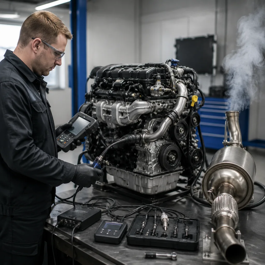
Cold-start pressure and time to build pressure
Hot idle pressure after oil temperature has stabilised, often above 90°C
Pressure at a fixed elevated speed, commonly 2,000 or 3,000 rpm
Oil grade, oil condition and service interval
Gauge connection point and gauge calibration status
Engine code, mileage and repair history
Use a calibrated mechanical pressure gauge wherever possible. A pressure switch alone is weak evidence in an oil pump failure oil pump investigation because wiring faults, connector corrosion, sludge in the switch port or switch calibration drift can all trigger false conclusions.
The pressure pattern matters more than one number. Low pressure only at hot idle often points to excessive bearing clearance, thin or fuel-diluted oil, or a marginal pump. Slow pressure build after start-up directs attention to drain-back, pickup restriction, suction-side air entry, relief valve leakage or a dry-installed pump. Very high cold-start pressure can indicate a sticking relief valve, incorrect oil viscosity or gallery restriction.
Generic pressure values are not enough. Many petrol engines may show roughly 0.7–1.5 bar at hot idle and 2.5–4.5 bar at 2,000–3,000 rpm, while diesel and high-output applications can run higher. The OE service limit for the exact engine is the control point. On marginal engines, a 0.2–0.3 bar gauge error can change the diagnosis.
Failure-mode map: what the symptom usually means
A simple failure-mode map prevents workshops, distributors and suppliers from arguing from different evidence. It also makes warranty classification faster because each complaint is tied to a likely cause group and a required inspection point.
Field condition
Main cause group
What to check first
Replacement decision
No pressure after installation
Dry pump, air at pickup, blocked pickup, wrong variant, installation error
Prime the pump, inspect pickup seal, confirm part number, check sump and pickup compatibility
Replace only after installation and variant errors are excluded
Cut open oil filter, inspect sump, galleries, pickup and bearing debris
Replace only with cleaning, pickup correction and documented root cause
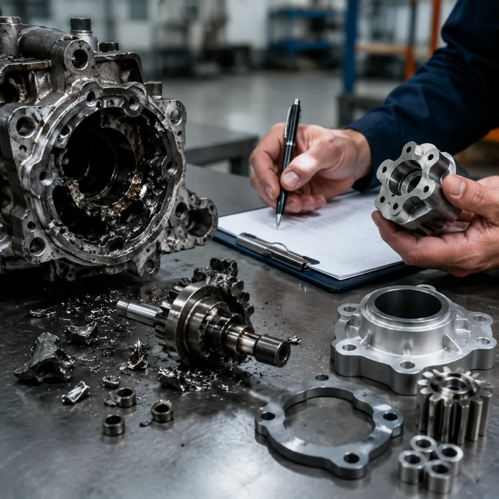
</tr></thead><tbody> </tbody></table>For B2B supply, this table should become part of the claim process, not just a workshop habit. A useful claim file includes vehicle application, engine code, mileage, oil grade, hot idle and elevated-speed pressure readings, installation date, photos of the sump and pickup screen, photos of the pump, and notes on related engine repairs. For a newly installed unit, request the batch code, carton label, installer invoice and confirmation that priming instructions were followed.
Separate first-fit defects from contamination failures. A clean pump that cannot generate pressure on a controlled bench test is a supplier risk. A scored pump with aluminium, carbon or bearing-metal particles embedded in the rotor pocket is usually a system-cleanliness or prior-damage problem. Buyers should ask suppliers to classify returned parts by failure mode, not only by “accepted” or “rejected” warranty status.
Failure modes that look like bad pumps but are not
Many returned pumps are damaged parts, but not defective parts. The distinction matters. If the field process keeps sending debris, air or wrong oil into a new pump, the next replacement may fail the same way.
Common non-manufacturing causes include:
Abrasive debris: Bearing material, machining chips, carbon and sealant fragments can score aluminium housings and rotor faces. Particles above roughly 100–200 microns may leave visible marks; finer debris can still accelerate wear.
Pickup restriction: Sludge, gasket pieces or a collapsed pickup screen reduces inlet flow and can cause cavitation. A wet screen may still be partly blocked, so it should be photographed before cleaning.
Excess RTV or wrong sealant use: Squeezed-out sealant can detach and block the pickup, gallery or relief valve. Over-application is a repeat-failure trigger.
Dry start after installation: Some pump designs need priming with clean engine oil or assembly lubricant. A dry rotor can scuff within the first 5–10 seconds of cranking.
Suction-side sealing faults: A cut, flattened or wrong-hardness O-ring can pull air into the pump without leaving external oil leakage. The sump may look dry outside while the pump is aerating oil inside.
Excessive engine bearing clearance: Worn main, rod or cam journals can consume pump output faster than the pump can maintain pressure.
Incorrect oil viscosity or degraded oil: Oil that is too thin at operating temperature, fuel diluted or heavily oxidised can expose marginal clearances.
Wrong application selection: Similar-looking pumps may differ in relief setting, pickup height, drive geometry or sump compatibility. A 1–2 mm pickup-position difference can be enough to create a field complaint.
A capable supplier helps control these risks before the claim happens. Installation cautions, fitment notes and variant warnings are not substitutes for the vehicle repair manual, but they reduce predictable errors across repair networks.
For higher-risk references, buyers should go deeper than catalogue matching. Request evidence of production controls for rotor width, housing pocket depth, valve bore diameter, spring free length, spring load, sealing dimensions and final cleanliness. The failure mode in the field should match a control point in the supplier’s process.
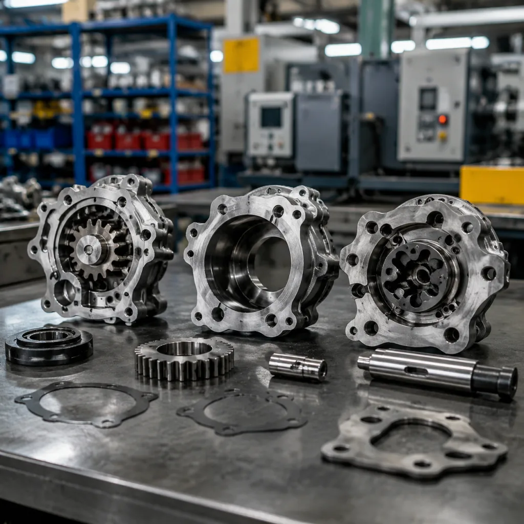
Bench inspection: read the removed pump before it is cleaned
The removed pump is evidence. Do not throw it away, wash it aggressively or mix it with other oily parts before inspection. The marks on the rotor, housing, relief valve and pickup port often show whether replacement alone will fix the engine.
Inspection sequence
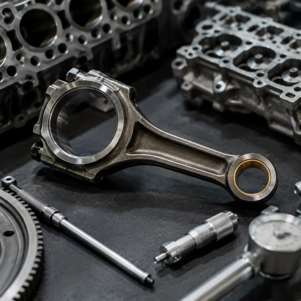
1. Photograph the pump as received. Capture the housing, ports, mounting face, drive interface and any visible debris. 2. Inspect the housing face and rotor pocket. Look for scoring, aluminium transfer, polished contact areas or deep circumferential marks. 3. Check the inner and outer rotor or gear set. Note pitting, chips, embedded particles, abnormal polish or tooth damage. 4. Measure clearances. End clearance, side clearance and tip clearance should be compared with the drawing or service limit. Typical gerotor end clearance is often around 0.03–0.10 mm, but the application drawing controls the result. 5. Test relief valve movement. The piston should travel freely through the bore without sticking or binding. 6. Measure the relief spring. Compare free length and load at compressed height with the supplier drawing. 7. Inspect suction sealing areas. Check pickup port surfaces, O-ring compression marks, gasket nicks and possible air-leak paths. 8. Review the drive interface. Look for rounded flats, shaft wear, spline damage, key damage or misalignment marks. 9. Inspect the sump and filter contents. Metallic debris, carbon, sludge and RTV fragments often explain the pump damage.
Damage patterns tell the story. Deep circular scoring usually means debris ingestion. A visually clean pump with low measured pressure may point to bearing clearance, relief leakage, air entry or wrong application. A seized relief piston may show varnish, burrs or trapped debris. Cavitation marks near the inlet side suggest restriction or air leakage rather than simple wear-out.
Use consistent tools: feeler gauges in 0.01 mm increments, a depth micrometer or dial indicator for end clearance, a micrometer or vernier for spring length, a spring tester for load and magnification for rotor scoring. If the pump is returned to the supplier, cap oily ports, bag the pump separately from the filter and keep debris evidence intact unless both sides agree on cleaning.
For procurement teams, bench findings should feed supplier review. Driventus applies incoming material checks, in-process machining controls and final inspection under its documented quality system. Depending on design, production control can include CNC-machined housings, controlled rotor profiles, spring load checks, critical-clearance verification and leak or flow validation.
Procurement spec deep-dive: what must be locked before purchase
An oil pump should not be sourced by photo match and cross-reference alone. Many engine families have several sump, pickup, drive or relief-pressure variants that look nearly identical in a catalogue.
A robust purchasing specification should lock these points:
Application fitment: engine code, model year range, fuel type and sump configuration
OE reference format where applicable, such as OE 06A… or OE 11251… when used in the buyer’s data
Pump type: gear, gerotor, chain-driven, crank-driven or balance-shaft-integrated
Housing material and sealing-face surface finish, including Ra target where leakage history exists
Rotor or gear material and heat treatment where specified
Relief valve opening range, piston movement and spring load control, including test oil viscosity and temperature
Mounting hole position, dowel location and drive interface geometry
Pickup tube, gasket, O-ring and sealant compatibility, including rubber material such as NBR, ACM or FKM where required
Cleanliness requirement for machined cavities and oil passages, preferably with particle limits or cleaning validation for programme supply
Packaging protection for sealing faces, machined ports and drive features, such as VCI bagging, port caps or formed trays
Batch traceability, production date code and inspection record availability
Commercial requirements should match risk. For catalogue aftermarket items, sample orders are often enough to confirm fitment, packaging and pressure behaviour before stocking. An existing pump may be available in lower cartons or mixed-SKU orders. A new housing, private-label box, special inspection record or non-catalogue variant may require tooling review, a production batch and longer lead time.
Unit price is usually shaped by annual volume, machining complexity, rotor material, included gaskets or pickup parts, testing content, packaging, incoterms and currency. Lead time is shortest for stocked references, longer for scheduled machining and assembly, and longest where new tooling, PPAP-style documentation, packaging artwork or material validation is required.
Driventus supplies oil pumps and related engine components through our catalog, including engine lubrication and powertrain parts for aftermarket distribution and programme supply. For non-catalogue housings, rotor changes, packaging, private-label documentation or buyer-specific inspection records, buyers can review custom manufacturing.
A strong RFQ package includes annual forecast, first order quantity, delivery market, OE and aftermarket references, sample or drawing, inspection requirements, packaging format, warranty process and requested documents such as dimensional report, material certificate or control plan. Supplier review may reference IATF 16949:2016, ISO 9001:2015 and REACH (EC) No 1907/2006 where relevant. These standards support evaluation; they do not prove vehicle-maker approval or endorsement.
Network scenario: stopping the same oil pump failure from returning
Consider a distributor seeing repeated oil pressure complaints on one engine family. Replacing pumps faster will not solve the problem if each branch diagnoses differently, cleans differently and records different evidence. The fix is a standard process that controls both part quality and installation variables.
Use this network workflow for high-risk applications:
1. Confirm oil pressure with a mechanical gauge before pump removal. Record hot idle and 2,000–3,000 rpm values. 2. Record oil grade, oil condition, filter brand and service interval where available. 3. Remove and photograph the sump, pickup screen, sludge and visible debris before cleaning. 4. Clean or replace the pickup tube if restriction, damage or poor O-ring sealing is found. 5. Inspect bearing condition if metallic debris is present in the sump or filter. 6. Flush or clean galleries when previous engine damage has released debris into the lubrication system. 7. Prime the replacement pump when required by design. Follow the repair manual if cranking without fuel or ignition is needed to build pressure before start. 8. Replace seals, O-rings and gaskets with the correct configuration for the engine code. 9. Verify hot idle and elevated-speed oil pressure after installation, then recheck for leaks after warm-up. 10. Keep the removed pump, filter and photographs if warranty review is requested.
The same workflow defines the documentation a supplier should provide with each shipment: fitment list, installation notes, inspection plan, packaging specification and warranty evidence requirements. Clear documentation cuts unnecessary returns and exposes real production trends faster.
For buyers moving thousands of pumps per year, claim tracking should be granular. Track rate by part number, batch, engine code and installer, not only by sales region. Even a claim rate below 0.5% deserves attention if complaints cluster around one application, one batch or one installation step.
Driventus can support distributors, wholesalers, OEM/Tier-1 suppliers and multi-location repair chains with oil pump programmes built around batch traceability and application validation. To discuss fitment data, MOQ, lead time, samples or private-label packaging, buyers may request a quote.
Frequently asked questions
No. Low pressure can come from pump wear, suction leakage, blocked pickup screens, incorrect oil viscosity, bearing clearance, relief valve faults or measurement errors. Confirm pressure with a mechanical gauge and inspect the sump, pickup and removed pump before assigning cause.
It depends on condition and design. Replace it if the screen is restricted, the tube is damaged or the O-ring sealing surface is worn. A clean new pump can fail quickly if the original pickup restricts flow or allows suction-side air entry.
No. IATF 16949:2016 is an automotive quality management system standard. It does not mean approval, endorsement or part release by any vehicle manufacturer.
If you are evaluating oil pump supply for aftermarket, repair-chain or programme purchasing, Driventus can review drawings, samples and fitment lists. Contact our team to compare specifications, documentation and availability at /contact.html