Oil Cooler How to Replace: OE Fitment Checklist
Replacing an oil cooler is a controlled maintenance task, not a simple parts swap. The right replacement has to match the original unit’s mounting pattern, port geometry, seal stack, and thermal duty. If those details are off, even slightly, the result can be cross-leaks, pressure loss, or a comeback for overheating. For workshop teams, that means disciplined removal, clean installation, and a proper leak test. For procurement teams, it means validating the part against the OE sample before release.
Driventus is an independent aftermarket manufacturer; brand names are referenced for fitment only. The guidance below covers selection, removal, installation, and post-fit checks for passenger cars and light commercial applications, with reference to published quality and material expectations such as IATF 16949:2016, ISO 9001:2015, and REACH (EC) No 1907/2006.
Replacement first: what has to match before you buy
The easiest way to get oil cooler how to replace wrong is to treat every cooler as visually similar. They are not. An oil cooler can be water-to-oil, air-to-oil, or integrated into the filter housing, and each version uses different ports, seals, and mounting details.
Before you order, confirm the following:
- OE number or validated cross-reference, for example `OE 06A107065` where applicable
- Cooler type: water-to-oil, air-to-oil, or integrated module
- Port thread, seal type, and port spacing
- Core size, bracket positions, and overall envelope
- Oil and coolant flow direction
- Vehicle engine code, transmission type, and emission package
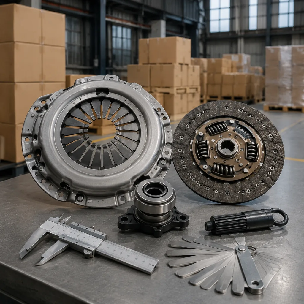
- Measured reference points: mounting center-to-center distance, port boss height, gasket land width, and overall thickness
For procurement, ask for a sample or dimensional drawing if the application is new or the supplier has no fitment history. The commercial side usually follows the technical risk: MOQ 50-100 pcs for catalog items, 20-50 pcs for pilot orders, and 1-5 pcs for sample validation; lead time is often 7-15 days for stocked parts and 20-35 days for new tooling or special finishes, depending on alloy, coating, and packaging requirements. A tighter drawing and approved sample usually cut quote variance and reduce returns.
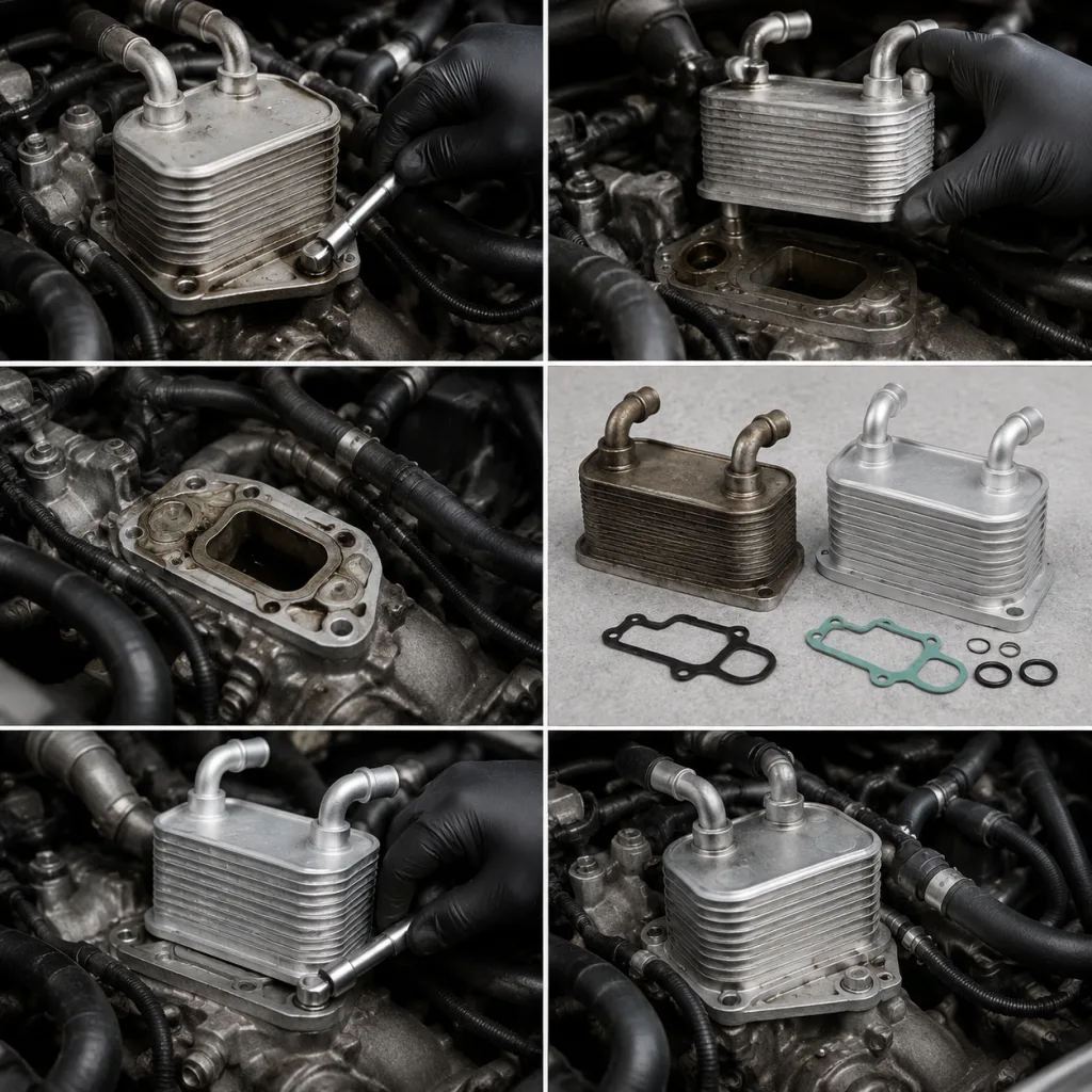
If you support fleets or distributor accounts, capture photos of the old unit, seals, and mating surfaces. Include a ruler in the image and note visible corrosion, damage, or contamination. That makes the replacement decision easier and the warranty trail cleaner.
Failure modes that cause repeat leaks or overheating
Most bad replacements fail for a small number of reasons. The part may fit the bolt pattern but still fail in service because the seal stack is wrong, the core is undersized, or the cooler is stressed during tightening.
Common failure modes include:
- Wrong port geometry, so the line does not seat correctly
- Seal mismatch, especially on integrated housings with non-standard O-rings
- Mating-face damage from scraping, prying, or previous over-torque
- Distorted housing from uneven fastening
- Insufficient thermal capacity for the engine duty cycle
- Cross-contamination from an old internal leak that was never flushed out
- Hose routing that places load on the cooler after installation
When the old unit shows internal mixing, do not reuse seals, hoses, or clamps that may have been chemically exposed. Flush the affected circuit before installing the new part. A practical flush target is to run fresh oil or coolant until visible contamination is gone and the drained fluid shows no discoloration or sludge. On severe contamination cases, replace the oil filter after the first heat cycle and inspect it again after 50-100 km or one fleet duty cycle.
A useful rule: if the replacement depends on forcing a line, elongating a slot, or “making the bracket work,” stop. That is not fitment. That is a warranty claim waiting to happen.
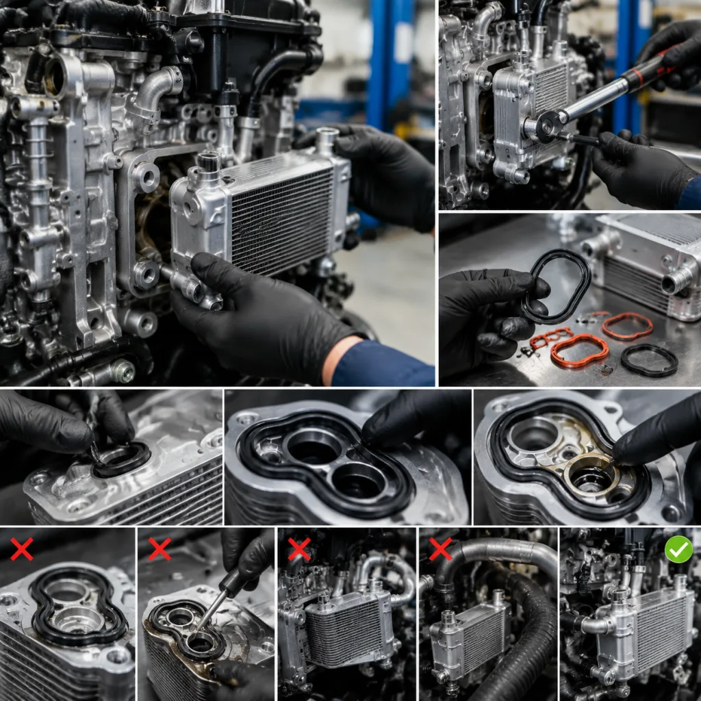
Removal sequence: keep the circuit clean and traceable
Drain fluids to a level below the cooler connections. On water-to-oil units, isolate both the oil and coolant sides before disconnecting lines. Keep debris out of the open passages; even a small amount can damage the new seals or score the valve body.
Step-by-step removal
1. Let the engine cool fully; target coolant temperature should be below 40°C before opening the system. 2. Drain oil and coolant according to the service procedure and capture the volumes for later refill comparison. 3. Label each hose, banjo, or quick-connect line with inlet/outlet direction and connection type. 4. Remove adjacent brackets or intake components if access is limited. 5. Unbolt the cooler evenly in a diagonal pattern to avoid warping the mating face. 6. Inspect the old seals, gasket imprint, and any evidence of sludge or coolant-oil contamination. 7. Measure the removed gasket compression set for diagnostic comparison only; any seal that has flattened more than about 15-20% of its original cross-section should be treated as failed.
If the unit failed from contamination, do not rush into the install. The cleaner the circuit is now, the fewer return visits later. Keep caps on open lines, bag the old cooler separately, and note the failure symptoms before disposal. A few photos and a clean workbench are often worth more than a long explanation later.
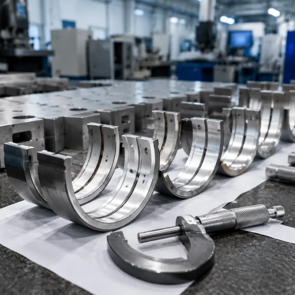
Spec check: dimensions, sealing faces, and thermal duty
Once the old unit is out, compare the replacement against the OE sample point by point. Dimensional match is the main control point. A cooler that is close but not exact can load the seal unevenly, restrict airflow, or distort under torque.
| Check item | What to verify | Why it matters |
|---|---|---|
| Mounting face | Flatness, hole pitch, bracket offset, and thread engagement depth | Prevents leaks and vibration |
| Port geometry | Thread form, seat angle, quick-connect profile, and chamfer | Ensures line compatibility |
| Seal surfaces | Groove depth, O-ring size, gasket width, and surface roughness | Protects against bypass and seepage |
| Core envelope | Length, width, thickness, fin coverage, and internal passage count | Preserves cooling capacity |
| Pressure rating | Oil and coolant side requirements, plus burst margin | Avoids burst or internal cross-leak |
| Material compatibility | Aluminium alloy, seals, coatings, and inhibitor compatibility | Supports REACH and service life |
| Thermal duty | Heat rejection target, operating temp range, and duty cycle | Confirms the part can control oil temperature |