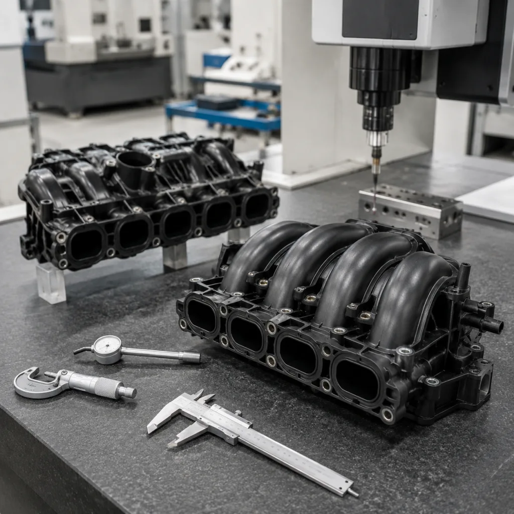
Intake manifold dimensions decide whether a part installs cleanly, seals under heat, routes hoses without stress, and delivers balanced airflow. In sourcing, the dimensional file is not a reference attachment. It is the basis for supplier qualification, PPAP-style review, incoming inspection, and warranty-risk control.
A manifold may share the same bolt pattern and still fail in the field. Common causes include shifted runner geometry, narrow gasket lands, flange distortion, injector boss angle error, sensor connector interference, or a throttle-body step that was not visible in a catalogue image. The result can be vacuum leakage, unstable idle, emission faults, poor cylinder filling, installation delays, and avoidable returns.
This article reframes the sourcing task around decisions, failure modes, and evidence: which dimensions to lock first, which tolerances matter, how material and process choices change risk, and what validation records should be reviewed before volume release. Driventus manufactures engine and powertrain components in Taizhou, Zhejiang, under IATF 16949:2016 and ISO 9001:2015 systems, with exports to more than 60 countries. Driventus is an independent aftermarket manufacturer; brand names are referenced for fitment only.
Start With the Interfaces That Can Stop Assembly
Do not begin the RFQ with the outer shape alone. Start with the interfaces that can create a leak, a fitment dispute, or an installation stop. The intake manifold controls air distribution and must align with the cylinder head, throttle body, EGR route, vacuum ports, sensors, injectors, brackets, and nearby engine-bay components.
For B2B sourcing, the following intake manifold dimensions should be part of the RFQ, sample approval plan, and first article inspection. If a feature touches a gasket, fastener, hose, connector, rail, or mating component, it needs a defined datum and acceptance method.
Dimension item
Why buyers should control it
Typical inspection method
Cylinder head port spacing
Prevents port mismatch, gasket overhang, and flow disturbance
CMM, optical scan, gauge fixture
Port opening height and width
Controls flow area and sealing margin
CMM, profile projector
Gasket land width and continuity
Supports stable gasket compression around each runner
CMM, visual gauge, section check
Flange flatness
Reduces vacuum leak and clamp-load variation risk
Surface plate, CMM
Bolt hole diameter and pitch
Allows installation without slotting, forcing, or rework
Pin gauge, CMM
Runner length and internal section
Affects torque curve, airflow balance, and cylinder distribution
CT scan, cut-section audit, airflow test
Throttle body interface
Confirms bore alignment and gasket compression
CMM, plug gauge
Sensor and vacuum port positions
Prevents harness strain, hose interference, and service-access issues
CMM, assembly fixture
Injector boss angle, where applicable
Controls spray targeting and fuel rail fitment
CMM, fixture check
Overall envelope
Confirms clearance to covers, ducts, brackets, heat shields, and body structures
3D scan, trial assembly
</tr></thead><tbody> </tbody></table>For OE cross-reference projects, part numbers should be used only for fitment identification, for example OE 06A… or OE 11251… when provided by the buyer. They should not be treated as evidence of vehicle manufacturer approval or authorisation.
Tolerance Decisions: Tight Where It Seals, Practical Where It Clears
A good tolerance plan separates functional dimensions from convenient-to-measure dimensions. Tight limits are justified on sealing faces, ports, bores, inserts, and mounting datums. They may add cost and scrap if applied to non-critical ribs or cosmetic outer walls.
Exact tolerances depend on engine design, gasket system, material, production process, and assembly stack-up. A machined aluminium flange can often hold a different window from an as-moulded polymer feature. A generous external envelope tolerance may be acceptable if no nearby part is affected. Use the matrix below as a sourcing benchmark, then adjust it to the application.
Cylinder head flange flatness: commonly controlled within 0.10–0.30 mm, depending on flange length, bolt load, and gasket design.
Port position to datum: typically ±0.10–0.30 mm for machined aluminium parts; wider limits may apply to moulded plastic features unless they are post-machined or fixture-controlled.
Bolt hole position: commonly ±0.15–0.30 mm relative to primary datums, with tighter control required where sleeves or inserts locate the part.
Throttle body bore concentricity: often controlled within 0.10–0.25 mm to avoid a step at the joint and maintain stable gasket compression.
Sensor boss position: commonly ±0.20–0.50 mm, depending on connector orientation, harness routing, and service-access requirements.
Sealing surface roughness: should be specified on the drawing rather than assumed; machined aluminium, die-cast aluminium, and moulded polymer surfaces require different controls.
Overall envelope: commonly ±0.50–1.50 mm for non-sealing external features, subject to clearance near heat shields, ducts, brackets, or covers.
The datum structure should reflect how the part is assembled. Cylinder head flange datums should control ports, bolt holes, and gasket location. Throttle body datums should control bore alignment and seal compression. A cosmetic outer wall should not become the primary inspection datum simply because it is easy to probe.
For critical characteristics, ask for capability data. Cpk or Ppk may be required by the control plan, especially for sealing faces, mounting features, inserts, and any dimension linked to leak rate, torque retention, or fitment complaints.
Material Choice Changes the Dimensional Failure Mode
The same nominal CAD model behaves differently in polymer, aluminium, and hybrid construction. That is why material selection is also a dimensional decision.
Plastic intake manifolds reduce mass and can integrate runners, resonance chambers, clips, vacuum circuits, and sensor bosses in one moulded body. The risk is not usually machining error; it is shrinkage, warpage, weld-line variation, insert movement, or creep after heat exposure. Aluminium manifolds offer stiffness and thermal resistance, but casting porosity, core shift, and machining datum control become central. Hybrid designs add another layer: bonded joints, metal inserts, rails, and brackets can move at different rates under temperature.
Material route
Dimensional strengths
Dimensional risks
Common controls
Glass-filled PA66 or similar polymer
Low mass, moulded complexity, integrated features
Shrinkage, weld-line variation, creep near inserts
</tr></thead><tbody> </tbody></table>Procurement specifications should also cover material declarations and restricted substances. For EU supply, REACH (EC) No 1907/2006 is relevant for chemical compliance. Depending on the target market and application, buyers may request material data sheets, resin batch traceability, aluminium alloy certificates, insert pull-out data, heat-ageing results, and evidence that recycled or reprocessed material is controlled.
One question is worth asking early: are the functional features created in the same tool cavity, machined after moulding, or located by secondary assembly fixtures? The answer can matter more than the nominal model. Cavity balance, cooling, insert placement, and post-mould conditioning can shift real intake manifold dimensions between prototype samples and mass production.
Sample Approval: Evidence That One Good Part Is Repeatable
A sample that fits one engine proves only that one sample fit one engine. Procurement approval needs evidence that the same result can be repeated across cavities, batches, operators, and shipments.
Driventus can align inspection reporting with customer formats through custom manufacturing, including dimensional studies for private-label, aftermarket, and OE-service programmes. A practical first article package should include the documents and records below.
Ballooned drawing linked to measured characteristics.
Full dimensional report from CMM, optical scan, CT scan, or approved gauges.
Material certificate and, where applicable, resin or aluminium batch traceability.
Leak test result with test pressure, duration, medium, and allowable pressure decay.
Thread, insert, and torque-retention checks.
Gasket compression and flange flatness records.
Airflow or runner-balance test results where required.
Assembly-trial notes for throttle body, sensors, hose fittings, brackets, and fuel rail where applicable.
Packaging drop or transport-protection review for exposed ports, flanges, and sensor bosses.
Control plan and inspection frequency for mass production.
For high-volume programmes, the supplier should also provide process flow, PFMEA, and control plan documentation consistent with IATF 16949:2016 expectations. ISO 9001:2015 supports general quality management, but automotive buyers usually need stronger evidence of risk-based process control, change management, traceability, and reaction plans when a key dimension moves out of control.
Validation Scenarios: When Correct Geometry Still Fails
Room-temperature inspection is necessary, but it is not the end of validation. Intake manifolds see thermal expansion, pulsating vacuum, boost pressure on turbocharged applications, vibration from the engine, and repeated clamp-load changes around fasteners and inserts.
The failure mode may appear only after the part has moved. A flange that passes flatness inspection can warp after heat ageing. An insert can hold torque during assembly but lose retention after cycling. A runner can measure correctly at the port while internal section variation creates airflow imbalance. Validation should therefore connect measured geometry to functional behaviour.
Relevant test items include:
Vacuum or pressure leak testing before and after thermal cycling.
Thermal shock and heat-ageing exposure to check warpage and flange movement.
Vibration testing with brackets, throttle body, sensors, and hose connections installed.
Burst or proof pressure testing for turbocharged applications.
Torque-retention testing at threaded inserts, bosses, and mounting points.
Runner airflow-balance testing to identify internal geometry variation.
Assembly trials with gaskets, fasteners, hoses, sensors, throttle body, and fuel rail where applicable.
Post-test dimensional checks on sealing surfaces, port locations, and critical mounting features.
Emission-related engine components may need to support vehicle-level compliance work under regulations such as ECE R-83, but a replacement component supplier should not claim vehicle approval unless formally certified for that scope. Driventus reports product validation data against agreed customer specifications and does not claim endorsement by any vehicle manufacturer. More information on audit controls and inspection practice is available through our quality system.
RFQ Walkthrough: What to Send Before Price Negotiation
Price discussions are faster when the dimensional problem is already defined. A clear RFQ reduces tooling disputes, engineering loops, and first-shipment delays. Buyers should provide CAD files, 2D drawings, target application data, annual volume, packaging requirements, and any OE cross-reference used for identification.
Driventus supports intake manifold and related engine component supply through our catalog, with project-specific engineering review when drawings, samples, or scan data are available.
Use this checklist before releasing a purchase order:
Confirm application range, engine code, market region, or fitment reference supplied by the buyer.
Define functional datums for flange, ports, bolt holes, throttle body interface, and sensor bosses.
Set acceptance criteria for flatness, port position, bore alignment, gasket land width, and leak rate.
Agree sample quantity, first article report format, submission timing, and approval workflow.
Confirm packaging design to protect ports, flanges, machined faces, clips, and sensor bosses.
Define batch traceability, date coding, private-label marking, and carton-label requirements.
Review MOQ, lead time, tooling ownership, engineering-change process, and spare tooling policy.
Confirm compliance documents for target markets, including REACH where applicable.
For distributors, dimensional interchangeability protects catalogue reliability and reduces returns caused by fitment disputes. For OEM and Tier-1 sourcing teams, it supports process approval, supplier comparison, and change control. For repair chains, well-defined intake manifold dimensions reduce bay time, prevent repeat labour, and make installation quality less dependent on technician improvisation.
Frequently asked questions
The most critical dimensions are cylinder head port spacing, port opening size, gasket land width, flange flatness, bolt hole position, throttle body bore alignment, and sensor or vacuum port locations. Runner geometry also matters because it affects airflow balance, torque response, and cylinder-to-cylinder consistency.
Yes. Driventus can review physical samples, 3D scans, and buyer-provided fitment references. For production approval, we still recommend a controlled drawing or agreed inspection specification so that key dimensions, tolerances, materials, and acceptance criteria are clear during mass production.
No. Driventus is an independent aftermarket manufacturer; brand names are referenced for fitment only. Product validation, inspection, and documentation are provided against agreed customer specifications, not as vehicle manufacturer endorsement.
If you are preparing an intake manifold RFQ, share drawings, samples, scan data, or target applications and we can review dimensional feasibility. To discuss sourcing requirements, [request a quote](/contact.html).