Idler Pulley How to Replace: Procedure and Checks
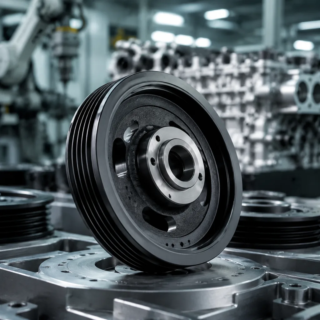
Replacing an idler pulley is a routine service task, but the replacement only works if the part matches the belt path, pulley geometry, bore size, bearing stack, and load rating. A mismatch can create belt noise, tracking drift, edge wear, or early bearing failure, especially once engine-bay heat, vibration, and contamination are added. For procurement teams, the visible pulley diameter is only one part of the specification. Material grade, bearing type, runout control, surface finish, and packaging all affect whether the replacement will hold up in service. Driventus is an independent aftermarket manufacturer; brand names are referenced for fitment only. This guide explains how to replace an idler pulley, which checks matter before installation, and what data to verify when sourcing an equivalent part. Our catalog, quality system, and custom manufacturing pages are linked below for teams that need supply support or OE-matching development.
What to confirm before replacement
Before fitting a new pulley, confirm the belt routing, pulley offset, mounting face condition, and fastener style. If the old part is noisy or seized, inspect the surrounding bracket, tensioner arm, and belt for secondary damage before ordering a like-for-like replacement.
Minimum checks
- Outer diameter, width, and flange profile match the removed part
- Bore and bearing series match the shaft or bolt
- Offset and face position match the belt line within the vehicle stack-up
- Seal type suits heat, dust, and splash exposure
- Fastener type, thread pitch, and tightening method are known
- Surface finish and edge break are acceptable for belt contact
For procurement, the question is not only whether the pulley fits physically. It is whether it keeps the belt aligned under operating load and over the required service interval. A 1.0 mm offset error can be enough to pull the belt toward one edge on narrow serpentine systems, so dimensional control matters as much as the visible shape. When the application is unclear, request an OE sample or drawing and confirm the shaft diameter, bearing OD, overall width, and installation stack-up before purchase.
Step-by-step replacement procedure
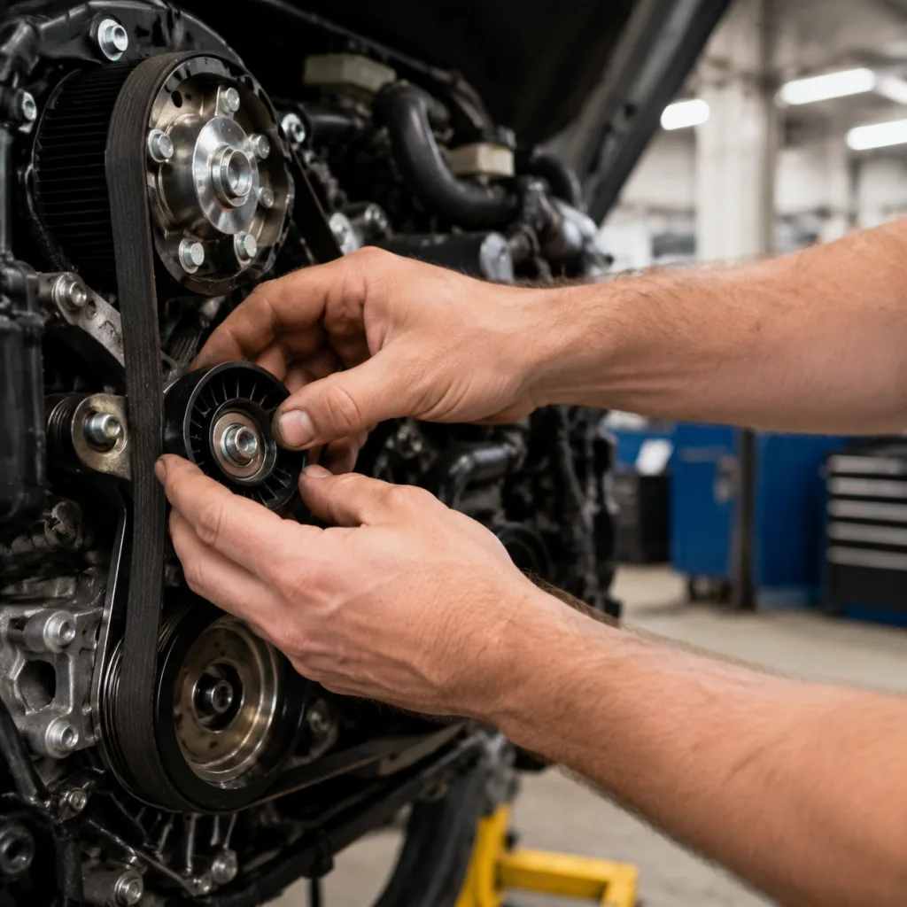
1. Disconnect the battery and allow the engine to cool to ambient if access is near hot components. 2. Record the belt routing with a photo or sketch before removing tension. 3. Release belt tension using the correct tensioner tool; do not lever directly on the arm unless the service procedure allows it. 4. Remove the belt from the idler pulley and adjacent pulleys. 5. Remove the fixing bolt or centre fastener and keep track of any spacers or washers. 6. Clean the mounting face and inspect the bracket for scoring, elongation, or corrosion. 7. Install the new pulley and tighten to the vehicle torque specification; many small accessory pulleys use roughly 20-40 N·m, but always follow the OEM data for the exact platform. 8. Refit the belt, release the tensioner, and verify tracking and tensioner movement. 9. Rotate the engine by hand, if permitted, and confirm there is no interference before starting. 10. Start the engine and check the belt path at idle, then after a short road test if the procedure requires it.
Use clean tools and avoid side-loading the bearing during installation. If the pulley uses a sealed bearing, do not wash or relubricate it, because that can damage the seals and shorten service life. During reassembly, confirm that the pulley spins freely without drag before the belt is fully tensioned. If the part uses a shoulder bolt, verify that the shoulder seats fully and that any spacer thickness matches the original stack-up, because improper stack height can preload the bearing and cause early noise.
Dimensional and material checks
A replacement pulley should be verified against a dimensional record, not just by visual comparison. In aftermarket supply, a common mismatch is a pulley that looks correct but has the wrong offset, bearing depth, or face finish. A buyer should request a drawing or inspection sheet and compare the critical dimensions against the OE sample or application data.
| Check item | What to verify | Typical control target | Why it matters |
|---|---|---|---|
| Outer diameter | Matches drawing and OE sample | Usually within ±0.10 mm to ±0.20 mm on controlled features | Affects belt wrap and speed |
| Width | Matches belt width and track | Usually within ±0.05 mm to ±0.15 mm | Prevents edge wear |
| Offset | Matches bracket and belt line | Often held to ±0.10 mm to ±0.25 mm | Avoids misalignment |
| Bore / bearing ID | Fits bolt or shaft correctly | Clearance depends on bearing class and fit | Prevents play and noise |
| Radial runout | Face and groove remain true | Common target ≤0.15 mm TIR, tighter for high-speed applications | Reduces vibration and belt wander |
| Face finish | Free from burrs and sharp edges | Edge break and surface finish per drawing | Reduces belt damage |
| Bearing seal | Suitable for heat and contamination | Grease fill and seal specification defined | Supports service life |
| Load rating | Matches accessory-drive duty | Ask for dynamic load and limiting speed | Prevents premature failure |