Fuel Rail How to Replace: Workshop and Sourcing Guide
Fuel rail replacement is controlled fuel-system work, not a casual bolt-on job. The right part must match injector spacing, mounting geometry, port sealing, pressure rating, and sensor interfaces, and the repair must protect technicians from leakage and vapour ignition. Multi-point petrol rails often operate around 3–5 bar; direct-injection rails can run far higher and require different tools, procedures, and validation. This guide stays focused on multi-point petrol injection and similar rail assemblies unless the vehicle service data says otherwise. It also gives procurement teams the checks to specify when sourcing replacement fuel rails for stock or programme supply. Always follow the vehicle service information for depressurisation, torque values, and scan-tool routines; do not assume one engine family uses the same rail across all model years. Driventus manufactures fuel rails and related engine components for B2B aftermarket and OEM/Tier-1 programmes under IATF 16949:2016 and ISO 9001:2015 controls. Driventus is an independent aftermarket manufacturer; brand names are referenced for fitment only.
When Replacement Is the Right Call
A fuel rail should not be replaced just because the engine runs lean, starts hard, cranks long, misfires, or smells of fuel. Those symptoms can come from the pump, filter, regulator, injector O-rings, evaporative lines, wiring, contaminated fuel, or a control fault. Replace the rail only when inspection confirms the rail itself is damaged, contaminated, dimensionally wrong, or no longer sealing.
Typical replacement triggers:
Visible seepage at a welded, brazed, crimped, plastic-welded, or machined joint
Corrosion pitting on the sealing land, injector cup area, bracket, or quick-connect bead
Bent or distorted mounting brackets after collision repair, engine removal, or poor previous installation
Internal contamination such as metal swarf, degraded hose particles, varnish, or rust that cannot be cleaned safely
Thread damage at mounting bosses, sensor ports, service ports, or retaining screws
Failed pressure-hold test after the injectors, feed lines, pump module, and regulator have been ruled out
Measured dimensional error versus the removed sample, such as injector pitch or bracket height that visibly loads the O-rings
For procurement teams, separate true rail-body failure from installation-related leakage. A high warranty rate may come from reused seals, dry assembly, misaligned injectors, contamination in the cup, or incorrect torque rather than the rail itself. Replacement instructions should state whether seals, clips, caps, regulator, sensor, or damper are included. For B2B programmes, a practical warranty screen is to request photos of the installed rail, removed seals, batch label, and pressure-test result before accepting a rail-body defect claim.
What Must Be Ready Before the Job Starts
Fuel systems can retain pressure after shutdown. Petrol is flammable, and vapour can collect around hot engine parts or workshop lights. Work in a ventilated area, keep ignition sources away, and use eye protection and fuel-resistant gloves. Where the service procedure allows, let the engine cool; many workshops aim for a surface temperature below 40°C before opening a fuel joint.
Item to verify
Workshop requirement
Procurement relevance
Fuel system pressure
Depressurise according to service procedure before disconnecting lines; typical port-injection systems may be 3–5 bar, but always verify
Product instructions should include a safety warning and never imply a universal pressure value
Replacement seals
Use new injector O-rings and line seals where specified; common injector O-rings are often 7–14 mm ID depending on system
Kits should include seals or clearly state exclusions and compatible material such as FKM where required
Rail geometry
Match injector spacing, bracket height, port angle, sensor position, and hose or pipe route
Dimensional drawings and control dimensions reduce catalogue errors
Material compatibility
Confirm ethanol-blend and fuel-additive compatibility for the target market, including E10, E15, and higher-ethanol markets where relevant
Relevant for EU, UK, US, Canada, Australia, and Brazil programmes
Cleanliness
Cap ports until installation; prevent lint, blast media, machining chips, and packaging debris entry
Packaging should use protective caps and clean bags; buyers can specify particle limits
Torque data
Use vehicle service data, not estimated hand torque; small rail bolts are commonly in the single-digit to low-teen Nm range but vary by engine
Avoid overloading bosses, brackets, inserts, and plastic manifolds
Electrical interfaces
Confirm sensor connector keying, harness reach, and clip orientation before final tightening
Avoid returns caused by visually similar rails with different sensor clocking
</tr></thead><tbody> </tbody></table>Useful tools usually include a scan tool, fuel pressure gauge where applicable, line disconnect tools, calibrated torque wrench, clean caps or plugs, absorbent pads, non-sparking work practices, and a fire extinguisher rated for flammable liquids. Disconnect the battery when the vehicle procedure requires it, especially near starter cables, alternator terminals, or exposed harnesses. Before opening the system, prepare a clean parts tray and label injector positions if the injectors will be reused; returning injectors to the same cylinder can simplify diagnosis if a post-repair misfire appears.
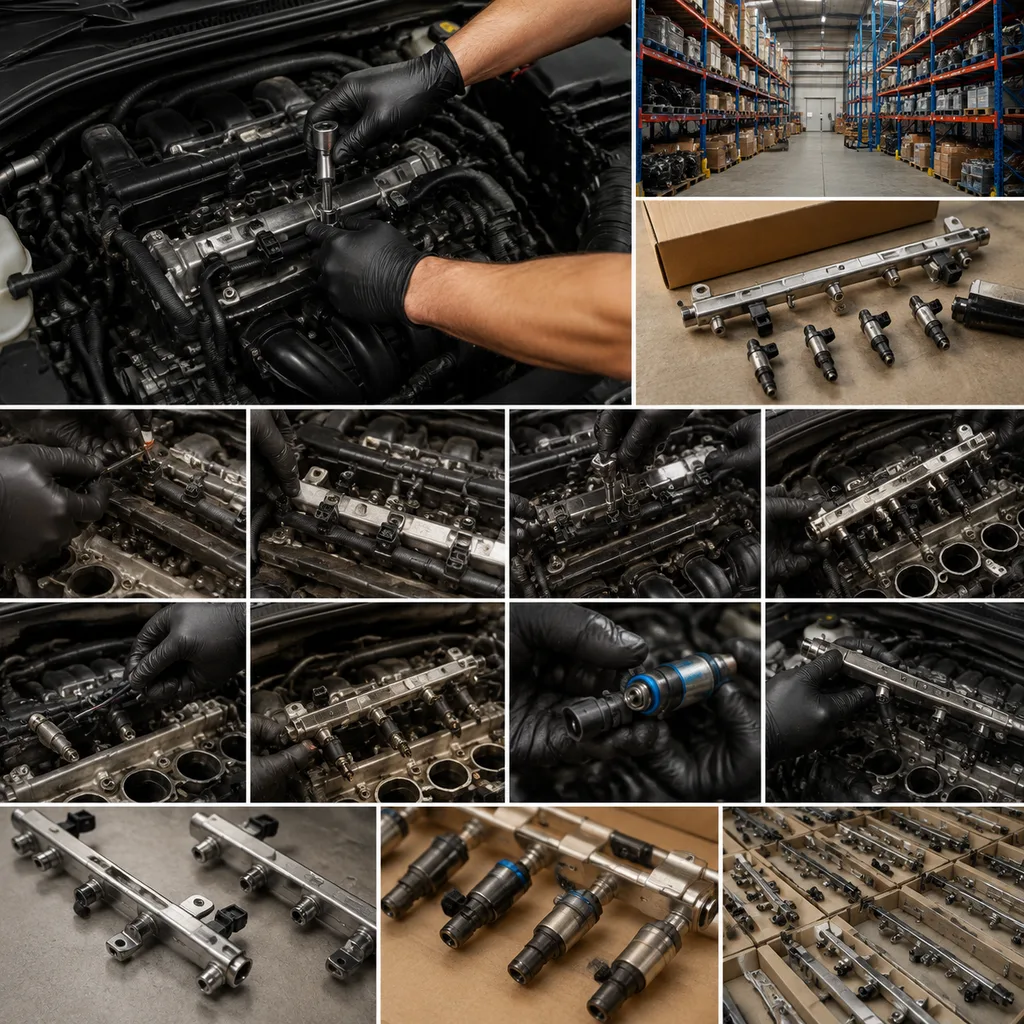
Fuel Rail How to Replace, Step by Step
The process below is general. Vehicle-specific service data always takes priority, especially for direct-injection engines, returnless systems, or rails with integrated pressure sensors.
1. Confirm the fault. Record diagnostic trouble codes, fuel pressure readings, freeze-frame data, long- and short-term fuel trims, and any visible leak points. Do not wash the area before documentation if the part is under warranty review. 2. Depressurise the system. Follow the service manual method, which may involve a fuel pump fuse or relay routine, scan-tool command, inertia switch procedure, or a pressure relief point. Wrap the connection with absorbent material before loosening and wait for any residual spray or vapour release to stop. 3. Disconnect the battery if required. This reduces ignition risk and protects electronic components during connector removal. Record radio or security procedures where needed. 4. Remove obstructing components. Intake ducts, engine covers, throttle-body ducts, brackets, harness retainers, and upper intake manifolds may need removal. Mark hose and connector positions if similar connectors are present. 5. Clean around the rail and injectors. Use compressed air carefully or a lint-free method so debris does not enter the injector bores. Avoid aggressive scraping near plastic manifolds and sealing cups. 6. Disconnect fuel lines and electrical connectors. Release quick-connect fittings with the correct tool. Do not pry against plastic line ends, sensor bodies, regulator housings, or damper caps. Cap opened lines immediately. 7. Unbolt the rail evenly. Loosen mounting fasteners in a balanced pattern. If injectors come out with the rail, keep them aligned to avoid bending tips, cracking plastic injector bodies, or cutting O-rings on the manifold edge. 8. Remove injectors and seals if required. Inspect each injector for cracked bodies, blocked filters, damaged pintle caps, bent terminals, hardened O-rings, or varnish deposits. Replace seals as specified and reject any injector that does not seat squarely in the replacement rail. 9. Compare old and new rails. Check injector bore count, centre-to-centre spacing, cup depth, mounting points, inlet and outlet orientation, sensor ports, regulator interface, bracket clearance, and line clip position. A 1–2 mm bracket or pitch error can be enough to load seals on some compact rails. 10. Install injectors with correct lubrication. Use clean fuel or fuel-compatible lubricant on O-rings where the service procedure permits. Do not use mineral grease unless specified, and do not twist injectors through dry seals. 11. Position the rail squarely. Press injectors into bores evenly and confirm each injector shoulder seats at a similar height. Start fasteners by hand, then tighten to the specified sequence and torque with a calibrated wrench. 12. Reconnect lines and harnesses. Listen or feel for positive engagement of quick-connects. Pull back lightly to confirm locking, fit secondary clips where used, and route harnesses away from hot exhaust or moving parts. 13. Prime and leak-check. Cycle the pump according to the service procedure without starting if possible. Inspect every injector seal, line connector, sensor port, regulator joint, and service valve. Wipe once, reprime, and recheck rather than assuming old residue is the only source. 14. Start, monitor, and road-test. Check pressure behaviour, short-term fuel trims, misfire counters, idle stability, hot restart, and leak status after heat soak. Reinspect after the cooling fan has cycled or after a short road test.
This is the core answer to fuel rail how to replace searches, but commercial programmes also need repeatable parts verification and documentation. Repair chains should standardise the checklist across locations to reduce comeback rates. A useful shop KPI is comeback leakage within 30 days per 100 rail installations, separated into rail-body defects, seal damage, wrong part, and workmanship causes.
Where Rails Fail in Real Use
The easiest way to cut comeback rates is to understand how rails actually fail. Many returns are not caused by the metal or polymer body at all. They come from fit-up, contamination, or a small geometry mismatch that only shows up after the engine heats and cools.
Common failure modes include:
Cut or twisted injector O-rings from dry installation
Side load created by incorrect injector pitch or bracket height
Debris in the injector cup or on the sealing land
Cracked plastic end fittings or sensor housings from over-prying
Corrosion at the bead, weld, or fastener boss after long service exposure
Incorrect quick-connect angle that leaves the line under tension
Pressure instability caused by an incompatible regulator, damper, or sensor interface
Hidden seepage that appears only after hot soak or vibration
That is why a leak-free prime is not the same as a verified repair. A rail can pass the first key-on test and still fail after the first heat cycle. If the same vehicle returns twice, look at installation history before condemning the replacement part. Compare injector seating height, rail bracket position, and seal witness marks. If the failure is repeatable across multiple vehicles, the issue is often catalogue fitment, not workshop technique.
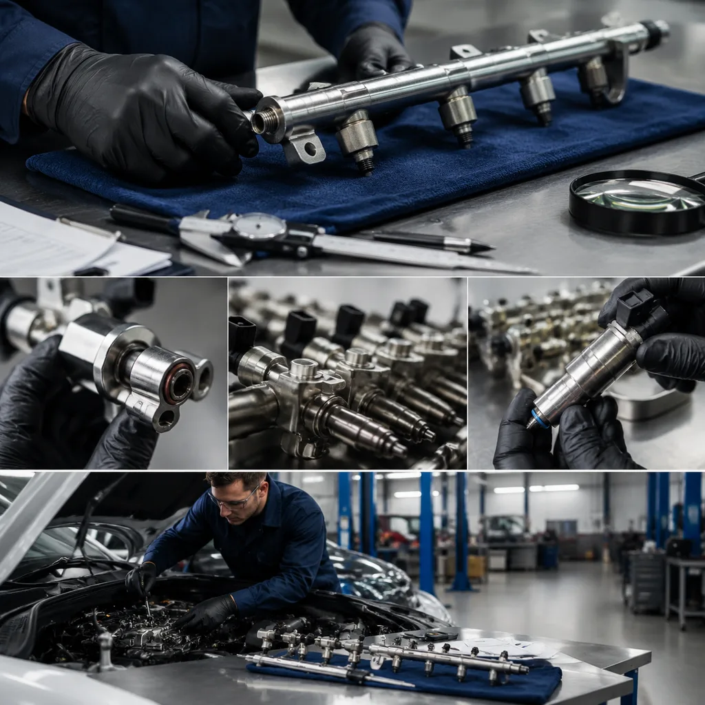
Fitment and Quality Checks Buyers Should Demand
A replacement rail should be treated as a precision fuel-handling component. Small deviations in injector pitch or bracket height can create O-ring side load, which may not leak during initial priming but can fail after thermal cycling. Buyers should agree control dimensions at RFQ stage instead of relying on catalogue pictures.
For distributor and repair-chain programmes, the release checklist should include:
Dimensional match: injector centre distance, bore diameter, cup depth, bracket datum height, fastener hole diameter, and port orientation checked against drawings or master samples. Where no OE drawing is available, create a receiving drawing from at least three verified samples.
Practical tolerances: define critical-to-fit dimensions, such as injector pitch, bracket plane, sensor-port depth, thread form, and quick-connect bead diameter. Many programmes control injector pitch and bracket datums within fractions of a millimetre, while non-critical bracket clearances may allow wider tolerance.
Pressure integrity: leak and burst validation suitable for the application pressure range. For a 3–5 bar port-injection rail, buyers commonly request 100% production leak testing above working pressure plus periodic burst or proof testing; exact pressures must match the application standard.
Surface condition: no burrs on injector cups, sensor ports, threaded bosses, O-ring lead-ins, or quick-connect lands. Cup lead-ins should be smooth enough not to shave O-rings during insertion.
Cleanliness control: capped ports, controlled flushing or filtered air blow-off, and particle-risk mitigation. For sensitive injector systems, specify a cleanliness method, sampling frequency, and acceptance limit rather than a vague “clean” requirement.
Material traceability: aluminium, stainless steel, coated steel, or engineered polymer grade recorded by lot, with heat or lot traceability where applicable.
Sensor and regulator compatibility: correct port depth, seal seat, thread form, retaining clip groove, connector clearance, and clocking angle.
Packaging protection: anti-impact separation, port caps, humidity control where required, readable batch labels, and carton compression strength suitable for pallet stacking.
Driventus applies process controls aligned with IATF 16949:2016 and ISO 9001:2015 through its quality system. For markets where chemical substances are controlled, buyers should also request material declarations relevant to REACH (EC) No 1907/2006 and confirm any RoHS or customer restricted-substance requirements. Emissions regulations such as ECE R-83 can be affected indirectly if fuel leakage, pressure instability, or incorrect injector seating changes fuel delivery, although replacement parts must be validated against the intended application rather than claimed as vehicle-manufacturer approved.
How to Source the Right Rail for Each Programme
For catalogue replacement parts, accurate cross-reference discipline is as important as manufacturing quality. Fuel rails often change by engine code, production date, emission package, sensor type, return-line configuration, or injector family. A rail that looks similar may place the pressure sensor 10–20 mm away from the harness path, use a different quick-connect angle, or shift a bracket enough to preload the injector seals.
When issuing an RFQ, include the following information:
Application list by market, engine family, engine code, production date range, emission level, and fuel type
OE cross-reference format where available, for example OE 06A… or OE 11251… when already used in the programme data
Required material, wall thickness or construction type, surface finish, coating, and corrosion requirement
Target working pressure, proof or leak-test pressure, burst requirement, and temperature range
Injector count, injector bore specification, O-ring size, cup depth, and injector retention method
Sensor, regulator, damper, service-port, quick-connect, and return-line configuration
Required documents: PPAP level where applicable, dimensional report, leak-test report, material declaration, control plan, inspection report, and warranty terms
MOQ, price, and lead time depend mainly on whether the rail is an existing Driventus item, a catalogue adaptation, or a new-tooled design. As a practical sourcing model:
Existing catalogue item: MOQ is usually driven by carton quantity and production batch economics; lead time is mainly stock status plus packing and export handling.
Minor change or private label: MOQ increases when dedicated labels, bags, caps, or customer-specific inspection are required; allow extra time for artwork approval and first-article checks.
Dimensional change or new tooling: price must recover fixtures, gauges, dies or moulds, validation, and PPAP work; lead time typically includes drawing confirmation, sample build, fitment trial, corrections, and production launch.
Unit price is normally affected by material grade, machining time, welding, brazing, or moulding process, number of ports, 100% leak-test time, included sensors, seals, clips, packaging density, inspection level, and Incoterms. Buyers comparing quotations should separate tooling or NRE, sample cost, production unit price, packaging cost, freight basis, and any certification or PPAP charge.
Driventus supplies fuel rails as part of our catalog and related engine components. For private-label, dimensional changes, bracket revisions, or programme-specific packaging, buyers can review custom manufacturing options. Driventus is an independent aftermarket manufacturer; brand names are referenced for fitment only.
What to Record After Installation
After installation, the technician should verify more than the absence of a visible leak. Fuel rail faults can appear during hot restart, vibration, or pressure decay after shutdown. A structured sign-off improves safety and gives distributors cleaner warranty data.
Recommended records include:
Pre-repair fault codes, freeze-frame data, and fuel pressure readings
Photograph of the removed rail and leak location, if applicable
Part number comparison and confirmation that the rail matches engine code and production date
Confirmation that new seals were fitted, with seal kit part number if separate
Torque confirmation for rail mounting fasteners where service data is available
Prime-cycle leak check result before starting the engine
Running pressure or scan-tool fuel pressure value where supported
Hot-idle, hot-restart, and short road-test result with post-test leak inspection
Fuel trim or misfire-counter check where the original complaint involved driveability
Batch number, date code, carton label, and invoice or job-card reference of the replacement part
If a vehicle returns with leakage, inspect the seal witness marks before assuming a rail defect. A cut O-ring, twisted seal, dry installation, injector misalignment, wrong injector height, damaged manifold bore, or debris in the cup can create a leak path. Useful evidence includes photos of the O-ring surface, injector seating depth, rail bracket position, and the exact leak point after priming. For high-volume repair chains, a one-page technician training note packaged with the rail often reduces repeat failures. Driventus can support distributors with inspection criteria, drawings, sample review, batch traceability, and agreed return-part analysis for programme supply.
Frequently asked questions
Yes, if the injectors pass inspection and are compatible with the new rail. The seals should normally be replaced, and injector tips, filters, bodies, electrical connectors, seating height, and O-ring grooves should be checked before reuse.
The main risks are fuel spray during depressurisation, fire from vapour ignition, and post-repair leakage from damaged or misaligned seals. Use the service procedure, new seals, correct line tools, a calibrated torque wrench, and a pressure leak check before road testing.
Provide application data, engine family, OE cross-reference format where available, rail material, pressure requirement, injector spacing, port configuration, packaging rules, forecast volume, MOQ expectation, and required quality documents such as inspection reports or PPAP where applicable.
If you are sourcing fuel rails for distribution, repair-chain stock, or a validated private-label programme, Driventus can review drawings, samples, application lists, MOQ targets, price drivers, and lead-time assumptions. To discuss fitment data, batch testing, packaging, or validation requirements, please [request a quote](/contact.html).