Front crankshaft seal symptoms of failure rarely present as a neat leak at the seal. Oil moves. It is flung by the crank pulley, carried by airflow, trapped on splash shields, and misread as an oil pan, timing cover, valve cover, or camshaft seal problem. For repair chains, distributors, and warranty teams, that misread becomes repeat labour, unnecessary parts replacement, dissatisfied customers, and claim disputes.
The seal works at the crankshaft nose, usually behind or near the crank pulley, harmonic damper, timing cover, or accessory drive. Its job sounds simple: keep engine oil inside while the crankshaft rotates. The operating conditions are not simple. Passenger and light commercial applications often use shaft diameters around 28–65 mm and seal widths around 7–12 mm. Oil temperature can exceed 120 °C, local cover temperature may be higher, and shaft speed moves from idle to more than 6,000 rpm. Heat, vibration, crankcase pressure pulses, installation quality, and shaft condition all decide whether the lip maintains contact.
This article is written for procurement and technical teams that need more than a symptom list. It separates visible evidence from root cause, sets out a workshop inspection path, highlights replacement risks, and defines sourcing controls for aftermarket programs. Driventus is an independent aftermarket manufacturer; any brand or OE references are used only for fitment identification.
Symptom map: read the oil pattern before naming the failed part
Start with the evidence pattern, not the assumption. A front crankshaft seal leak usually begins at the crankshaft nose, but the first visible oil may appear on a belt, splash shield, alternator housing, engine mount, or lower sump area. On transverse engines, the pulley often throws oil outward in a radial pattern. On longitudinal layouts, oil may track down the timing cover and collect at the front sump joint, which makes the oil pan look guilty.
Use the table as a decision aid when front crankshaft seal symptoms of failure are suspected:
What you see
What it usually suggests
What to check next
Fresh oil ring within 10–30 mm of the crank pulley or damper hub
Leakage at the seal lip or crankshaft nose
Remove covers as needed and inspect the seal lip, shaft track, and bore
Radial oil spray after a 5–15 km road test
Pulley rotation distributing oil from a front leak
Check belt contamination, pulley runout, and harmonic damper condition
Burning oil smell after driving
Oil reaching hot covers, brackets, or nearby exhaust-side parts
Trace the highest wet point before replacing parts
Belt squeal, slip, or glazing
Oil reducing friction on the accessory belt
Repair the leak and replace contaminated belts where required
Oil droplets on the undertray after overnight parking
Oil spreading under airflow and then collecting after shutdown
Clean, road test, and recheck the leak path
Leak returns within days or 500–2,000 km after replacement
Shaft groove, wrong install depth, damaged bore, crankcase pressure, or wrong seal design
Inspect the crankshaft surface, PCV system, housing, and installation method
</tr></thead><tbody> </tbody></table>A marginal seal may stay quiet at idle. Under load, oil temperature rises, shaft speed increases, and crankcase pressure changes. That is when the leak often declares itself.
For fleet and repair-chain workflows, record the facts before approval: mileage, oil specification, engine code, recent timing belt or timing chain work, crank pulley service history, and earlier front-engine leak repairs. Light misting with no droplet after cleaning can be monitored. A visible droplet at the lip, oil in the belt path, or measurable oil loss should be treated as an active leak.
Failure modes that make a new seal leak again
Age can harden a sealing lip. That is the easy explanation, and sometimes it is correct. But early leakage after replacement usually points to a system fault or process error, not simply a bad seal.
Seal materials also behave differently. NBR is often used for moderate oil and temperature exposure. ACM generally handles more heat than standard NBR. FKM is selected where higher temperature and oil-chemistry resistance are needed. PTFE is used in designs requiring low friction or dry-install lip behaviour. A part that looks similar on the bench may not work the same on the engine.
Failure modes worth separating:
Crankshaft running-surface wear: A polished groove, corrosion line, burr, or pitting interrupts lip contact. If a groove catches a fingernail, often around 0.05 mm or deeper, review sleeve use or alternative installation depth.
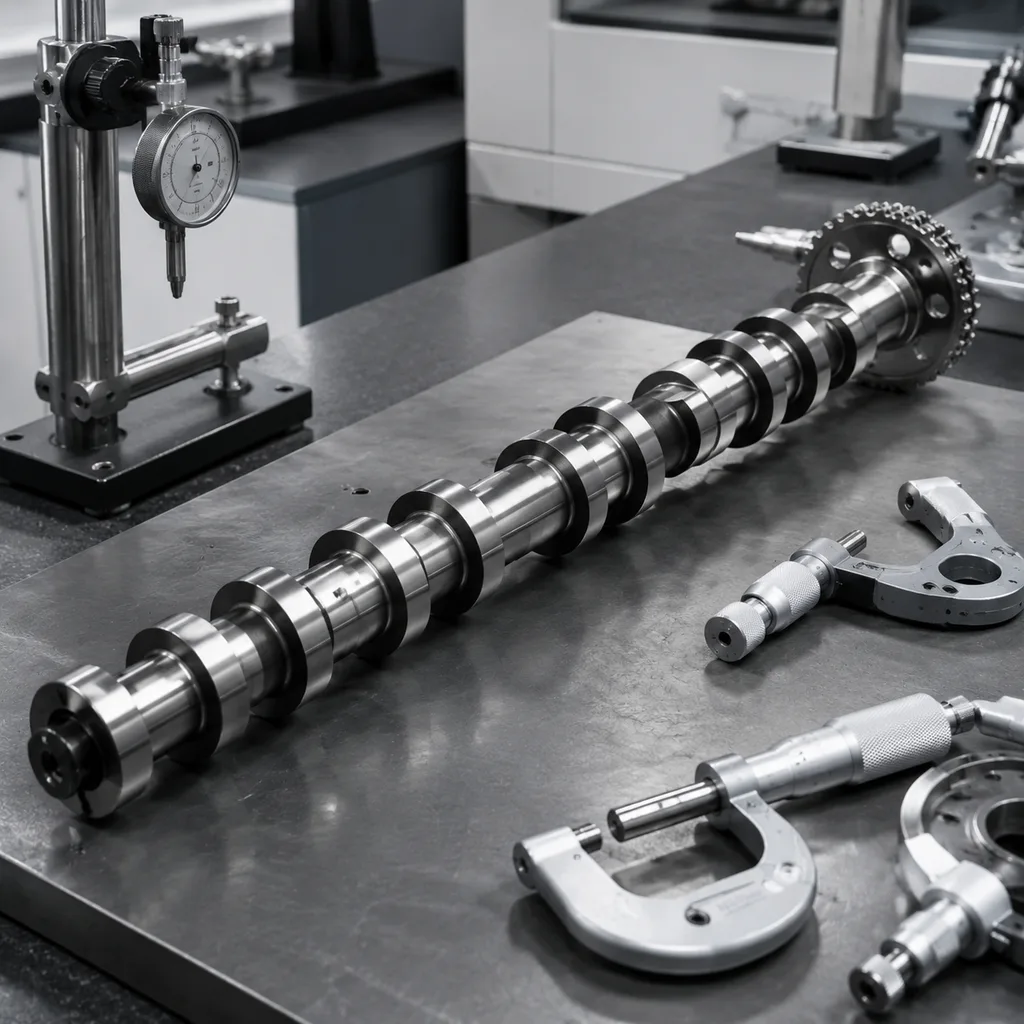
Pulley or harmonic damper runout: Wobble changes dynamic lip loading and raises heat. Where no OE limit is available, many workshops investigate total indicated runout around 0.10–0.20 mm or higher.
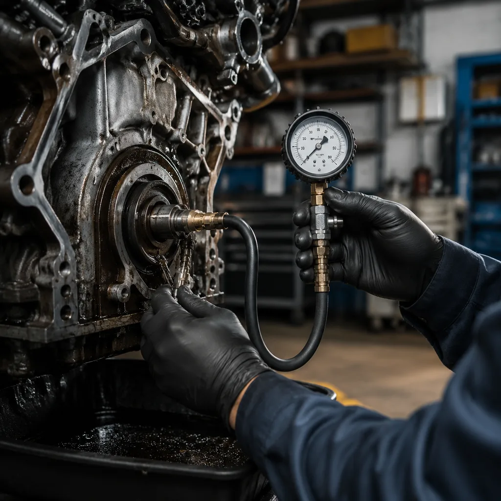
Restricted crankcase ventilation: Positive crankcase pressure can push oil past a sound seal, especially during acceleration, high load, or high temperature. Check pressure or vacuum with a manometer at idle and 2,000–3,000 rpm.
Installation damage: Cocked fitting, hammer impact, dry-start damage, folded lips, sharp crank edges, or a dislodged garter spring can cause immediate failure. A tilt of only 0.5–1.0 mm across the diameter can distort lip load.
Contamination: Abrasive dust, metal particles, old gasket material, and loose sealant can cut the lip or score the shaft. Finish cleaning with lint-free cloth and compatible solvent. Do not abrade the sealing track.
Sealant misuse: Excess sealant can hold the seal out of position, contaminate the lip, or break loose into the oil system. If sealant is specified, keep the bead controlled and away from the lip.
Material or design mismatch: Shaft speed, oil chemistry, temperature, crank rotation, and housing design may require a specific elastomer, PTFE construction, or directional lip.
Damaged housing bore: Scratches, corrosion, ovality, or removal damage in the timing cover can leak around the outside diameter. If oil appears around the OD rather than the lip, measure the bore at several positions.
This distinction protects both buyer and supplier. A useful warranty form should separate dimensional nonconformance, material concern, installation damage, shaft condition, housing condition, crankcase pressure, and application-data accuracy. Without that split, every return looks like a product defect even when the engine or repair process caused the failure.
Workshop diagnostic sequence: prove the leak before removing the seal
The best diagnostic step is often cleaning, not disassembly. Oil from a valve cover, camshaft seal, timing cover joint, vacuum pump, oil pan joint, or oil filter housing can all collect near the crank pulley. UV dye can help, but more dye is not better; overdosing stains too much area and hides the path.
Follow this sequence when the front crankshaft seal is under suspicion:
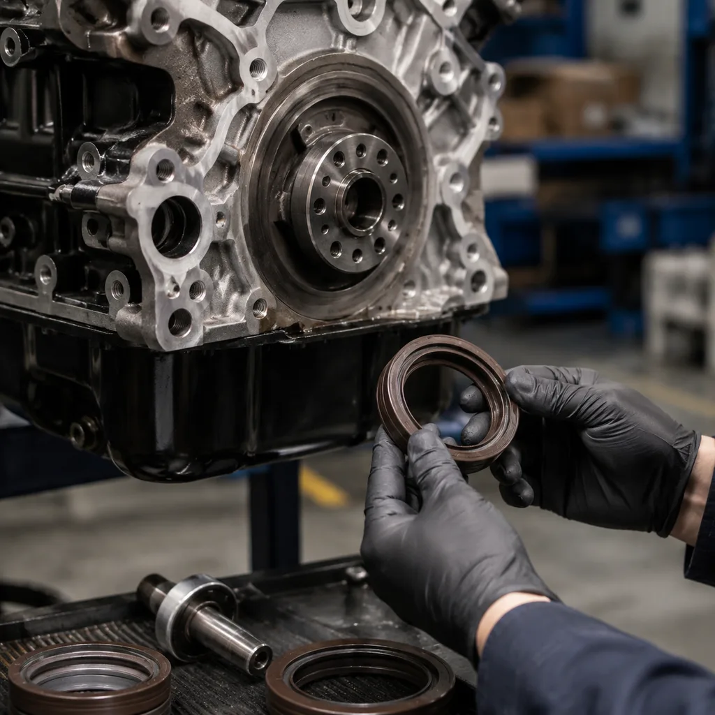
1. Identify the fluid. Engine oil, transmission fluid, power steering fluid, and leftover service fluid can migrate along covers and brackets. Check colour, smell, viscosity, and the highest wet point. 2. Clean and photograph the baseline. Degrease the front cover, crank pulley area, lower shield, and belt-adjacent surfaces. Photograph the dry area before running the engine. 3. Inspect from the top down. Rule out valve covers, cam covers, vacuum pumps, oil filter housings, and timing cover joints before calling the crank seal. 4. Check crankcase ventilation. A restricted PCV or breather path can overwhelm the lip. Record vacuum or pressure readings if a warranty claim may follow. 5. Expose the belt-cover area as required. Look for oil emerging from the lip, the outside diameter, the housing bore, or an adjacent timing cover joint. A mirror or borescope can avoid unnecessary teardown. 6. Evaluate the crank pulley and harmonic damper. Look for rubber separation, cracks, wobble, scoring, corrosion, and tool damage. Confirm visible wobble with a dial indicator. 7. Assess belt contamination. Oil on an accessory belt or timing belt can create noise, slip, tracking problems, or rubber degradation. Photograph the contact zone before removal. 8. After removal, inspect the shaft and bore. Burrs, corrosion, sealant residue, grooves, and cover damage must be corrected before fitting the replacement. Use a micrometer for shaft OD and a bore gauge or calibrated caliper for the cover bore where practical. 9. Document the claim file. Capture the leak path, shaft surface, removed seal, packaging label, batch code, mileage, engine code, oil grade, install date, and distance since installation.
Distributors supplying several workshop networks can turn this into a one-page bulletin. It reduces false returns and helps branches order related parts before the vehicle is already dismantled. For high-volume programs, use simple disposition codes: product dimension, material or lip damage, installation damage, related-component issue, engine pressure issue, catalogue mismatch, or no fault found.
Seal specification deep dive: small part, strict controls
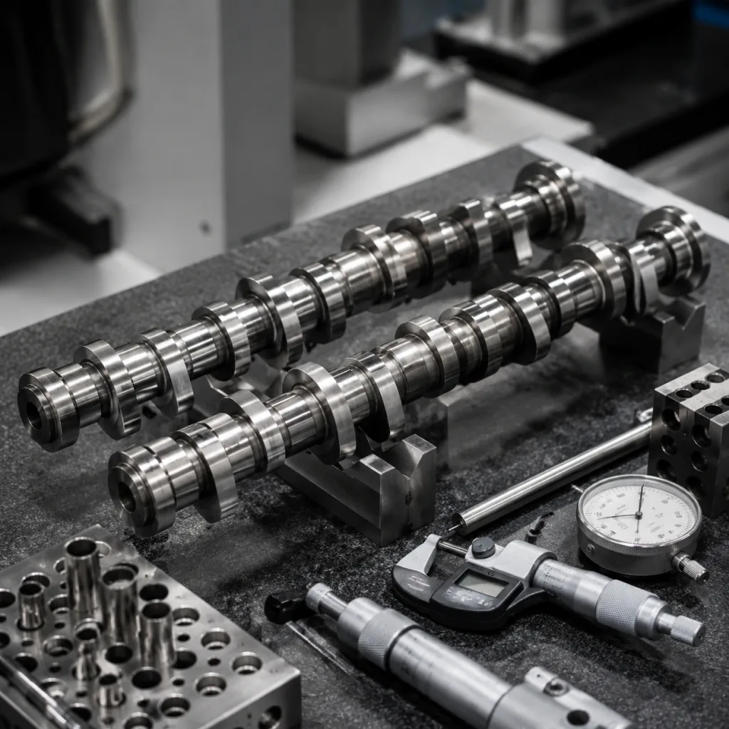
A front crankshaft seal is not defined only by inside diameter, outside diameter, and width. Field life depends on lip geometry, radial load, spring retention, rubber-to-metal bonding, case rigidity, dust exclusion, shaft-contact design, and packaging condition.
When qualifying a supplier, ask for these specification points rather than relying on visual matching:
Dimensional match: Confirm OD, ID, width, chamfers, case profile, lip position, and installation-depth references against drawings or approved samples. Typical drawing tolerances may include OD within ±0.05–0.10 mm and width within ±0.10 mm, but the approved drawing governs.
Material declaration: Request elastomer or PTFE family, metal insert information, hardness target, temperature guidance, oil-compatibility guidance, and ageing-test summary. Colour is not a material specification.
Lip geometry: Check primary lip angle, contact band, dust lip, and directional features where applicable. Directional pumping ribs must match crankshaft rotation; reversed features can pump oil outward.
Radial force method: For spring-loaded designs, agree on test method, mandrel size, speed, and sample size. Values from different methods may not be comparable.
Garter spring retention: The spring should not dislodge during handling, packaging vibration, or normal installation-tool contact.
Bonding integrity: For metal-cased seals, rubber-to-metal bond failure, blistering, or case corrosion can create outside-diameter leakage.
Bore fit and case rigidity: Press fit is application-specific. Excessive OD growth, case waviness, or poor rigidity can distort aluminium covers during installation.
Packaging protection: Fine lips and PTFE edges need protection from deformation, dust, and crushing. Individual bags, trays, caps, or controlled inserts are preferred for export handling.
Traceability: Each carton should connect to batch, production date, inspection record, packaging label, and retained sample where agreed.
Management standards such as IATF 16949:2016 and ISO 9001:2015 do not define the exact lip profile of a crankshaft seal. They do support process control, traceability, calibration, corrective action, and documented inspection. For EU supply, material obligations such as REACH (EC) No 1907/2006 may also apply. Buyers can review Driventus front engine components in our catalog and the engine range at /products/engine-components.html.
Distributor sourcing decision framework: control fit, variation, and claims
In B2B supply, the risk is not only one leaking vehicle. The bigger risk is variation across branches: one carton fits, another distorts; one batch survives storage, another arrives with deformed lips; one engine split is catalogued correctly, another creates wrong-part returns.
Use the controls below when approving or expanding a front crankshaft seal program:
Control item
What to verify
Why it matters
Application data
Engine code, model year range, engine family, production split, crankshaft OD, timing cover type, and buyer-supplied OE reference format such as OE 06A…
Prevents catalogue misapplication and wrong-part returns
Dimensional inspection
ID, OD, width, case form, chamfer, lip position, and installation depth against drawing or approved sample
Confirms physical interchangeability
Material selection
NBR, ACM, FKM, PTFE, or specified compound, with hardness and ageing target
Matches oil chemistry, heat exposure, shaft speed, and engine design
Lip design
Spring-loaded, PTFE, dust lip, directional lip, or application-specific profile
Avoids substituting a visually similar but functionally different seal
Batch traceability
Lot code, inspection record, production date, retained sample, and carton label format where agreed
Supports warranty investigation and containment
Packaging validation
Individual lip protection and prevention of compression set during storage and sea or air freight
Reduces deformation, dust contamination, and transit damage
Change control
Written notice for material, tooling, process, supplier, inspection method, or packaging changes before shipment
Avoids unapproved variation after approval
Claim feedback loop
Return analysis categories, photo documentation, batch quarantine, and 8D or corrective-action timing
Separates product defects from installation or engine-condition issues
</tr></thead><tbody> </tbody></table>Commercial planning should match the validation stage. Sample or PPAP-style approval runs may use 20–100 pieces per reference for dimensional and fit checks. A first commercial order is often set by carton quantity or tooling economics, commonly 500–2,000 pieces for fast-moving references. Long-tail references may be consolidated by family, compound, or shipment.
Price is shaped by compound choice, metal case complexity, PTFE versus elastomer construction, tooling status, inspection level, private-label packaging, and annual volume. Lead time should be split into tooling or sample time, approval time, production time, and freight. Stocked references can move quickly; new or customised seals may need several weeks for tooling, trial production, inspection, and packaging approval.
Driventus manufactures engine and powertrain components in Taizhou, Zhejiang, and exports to more than 60 countries. Our quality system is structured around IATF 16949:2016 and ISO 9001:2015 controls, including incoming inspection, in-process checks, final inspection, traceability, and corrective action. For application-specific requirements, buyers can discuss custom manufacturing, including sample-based development, drawing review, packaging specification, kit configuration, and private-label supply.
Service scenario: when the seal job should become a front-engine repair kit
A front crankshaft seal can be cheap while the access labour is not. If oil has reached belts, pulley rubber, timing components, or the harmonic damper, treating the seal as a standalone item may create a comeback.
During service, check the surrounding parts deliberately:
Replace an oil-soaked accessory belt instead of cleaning and reusing it. Glazing, edge swelling, cracking, saturation, or noise after cleaning makes replacement the safer choice.
Inspect the harmonic damper rubber layer for swelling, cracking, separation, offset between hub and outer ring, missing rubber, or visible wobble.
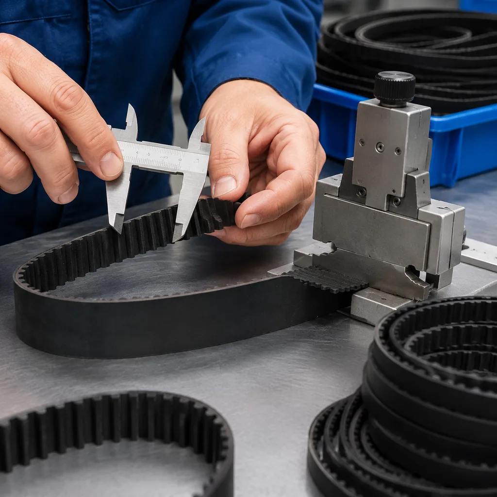
Check the timing belt if the engine uses a belt behind the front cover. Oil on a timing belt is higher risk than oil on an accessory belt because tooth shear or tracking failure can damage the engine.
Replace a contaminated timing belt where vehicle service information or workshop policy requires it. Many repair chains mandate replacement once oil reaches the tooth surface or belt edges.
Renew single-use crank pulley bolts when the service procedure specifies replacement. Torque-to-yield bolts should not be reused unless service data permits it.
Inspect the crankshaft running surface for grooves. Use an approved repair sleeve only when suitable; sleeve thickness changes shaft diameter and must match seal design and clearance.
Clean the seal bore without scratching aluminium timing covers. Plastic or brass tools are usually safer than hardened steel picks near the bore shoulder.
Avoid unnecessary sealant. Excess material can prevent full seating or migrate to the lip and oil circuit.
Follow the seal-specific lubrication rule. Conventional elastomer lips and PTFE lips may have different installation requirements. Some PTFE seals require a waiting period before crankshaft rotation.
Install squarely with the correct driver. The tool should contact the seal case, not the lip, and seat to the specified depth or flush reference.
For category managers, this is where kits can reduce branch errors. A front-engine leak repair kit may include the seal, compatible gasket, sleeve where applicable, crank bolt where specified, related belt, and installation note. Kits usually require higher MOQ than loose seals because of packaging labour and mixed components, but they can lower comeback cost and simplify branch stock. Driventus can support distributors with component supply or kit packing according to agreed drawings, samples, and application lists. To discuss volume, packaging, or validation requirements, buyers may request a quote.
Frequently asked questions
Yes. Oil from valve covers, timing covers, camshaft seals, oil pan joints, oil filter housings, or vacuum pumps can run toward the crank pulley area. Clean the area, run the engine for 10–15 minutes and/or complete a short road test, then inspect from the highest wet point downward before replacing the front seal.
No. If the crankshaft surface is grooved, the pulley has runout, crankcase pressure is excessive, the bore is damaged, or the seal is installed incorrectly, leakage can return quickly. The shaft, bore, ventilation system, installation depth, and related pulley components should be checked during repair.
Verify application data, dimensions and tolerances, elastomer or PTFE material, lip design, packaging protection, traceability, MOQ and lead-time assumptions, and quality controls under IATF 16949:2016 and ISO 9001:2015. For EU supply, request relevant material declarations for REACH (EC) No 1907/2006.
If your team is evaluating front crankshaft seals for distribution, repair-chain programs, or private-label supply, Driventus can review drawings, samples, application data, MOQ targets, packaging specs, and validation requirements. Contact our engineering and sales team at /contact.html