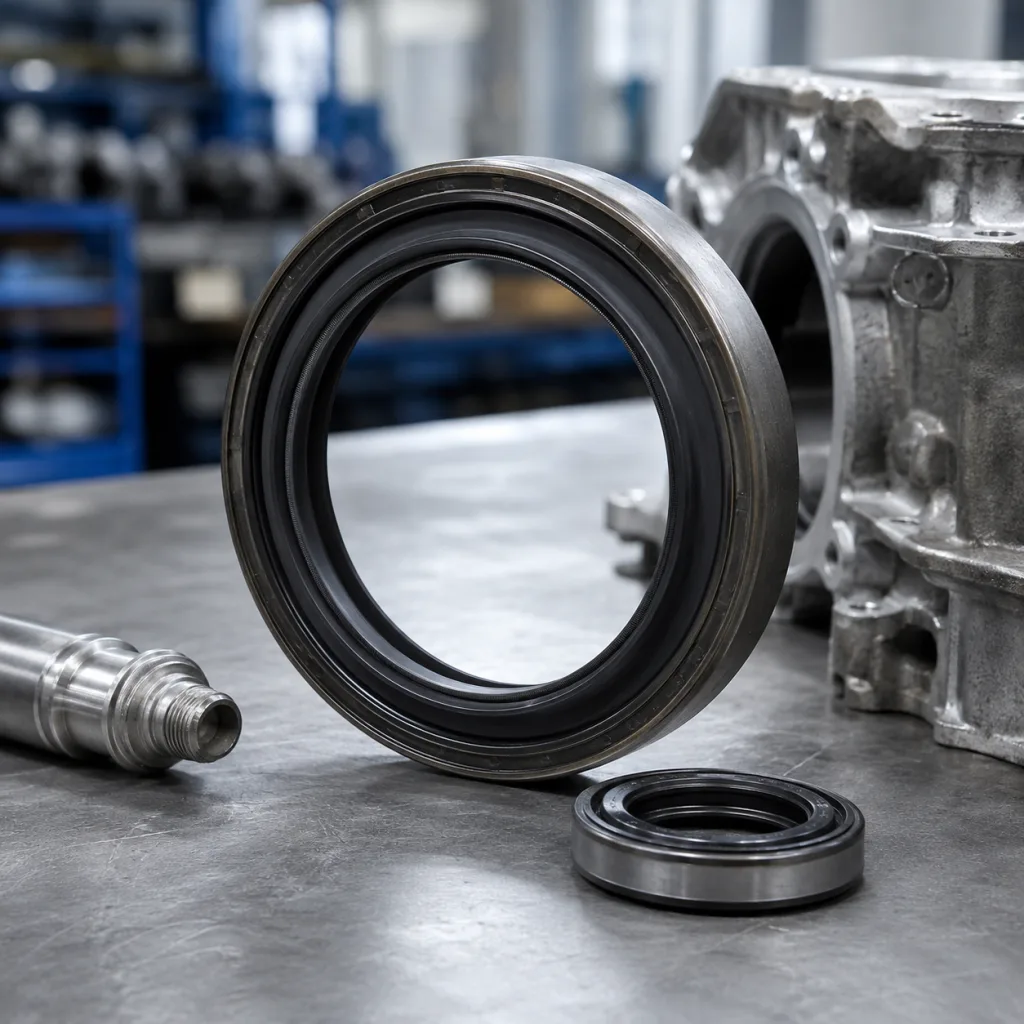
Front Crankshaft Seal Specifications for Procurement Teams
Front crankshaft seal specifications are typically defined by shaft diameter, housing bore, seal width, lip design, spring load, material, and temperature range. For procurement teams, the key issue is not just nominal size but the full fit-and-function picture: tolerance stack-up, crankshaft journal surface finish, and the operating fluid environment. A seal can match the drawing and still leak if the elastomer is unsuitable, the garter spring load is off, or the running surface falls outside specification. Driventus supplies front crankshaft seals for aftermarket distribution, repair networks, and industrial sourcing programmes. Driventus is an independent aftermarket manufacturer; brand names are referenced for fitment only. The guidance below is written for buyers who need dimensional control, repeatable output, and documented quality. Published standards such as IATF 16949:2016, ISO 9001:2015, and REACH (EC) No 1907/2006 remain relevant when comparing suppliers and validating material compliance.
Core dimensions to specify
When buying a front crankshaft seal, the minimum data set should include shaft diameter, housing bore, and seal width. Add lip style, installation direction, and whether the part is a single-lip or dual-lip design.
Specification item
Typical procurement note
Buyer target / tolerance guidance
Shaft diameter
Match crank snout diameter; confirm metric or imperial
Verify nominal size to the drawing and confirm the allowable shaft tolerance before release
Housing bore
Verify interference fit in the front cover or timing case
Require the bore spec, plus ovality and concentricity limits
Seal width
Check axial space and flush-mount requirement
Confirm installed width against the cover pocket depth and retain a max stack-up allowance
Lip design
Single lip, double lip, or dust lip
State the exact lip profile and whether an auxiliary dust lip is required
Spring type
Garter spring or springless PTFE design
Specify spring presence, spring wire material, and target radial load range
Rotation
Bi-directional or rotation-specific
Confirm rotational direction at the crank pulley end and the expected speed band
Service fluid
Engine oil, ATF, or mixed contamination exposure
State fluid exposure, splash frequency, and any fuel or coolant contamination risk
Operating temperature
Continuous and peak temperature
Define continuous service range and short-term peak temperature before quoting
</tr></thead><tbody> </tbody></table>For OE-style replacement work, buyers should request the OE cross-reference first, then confirm the actual measured dimensions. A nominal match does not guarantee the same compression load, lip position, or sealing behavior in service. As a practical sourcing rule, ask for the dimensional drawing with controlled tolerances, not only the part number, and require first-article samples when the application is safety- or downtime-critical.
Materials and sealing elements
Material choice drives heat resistance, oil compatibility, and service life. The most common elastomers are NBR, FKM, and HNBR. PTFE is used where low friction and extended dry-running tolerance are required.
NBR: economical, suitable for standard engine oil exposure, with moderate heat resistance, typically used where continuous temperature stays around 100–120°C and peak conditions are limited.
HNBR: improved heat and ozone resistance, common in higher-temperature engine applications, often selected when continuous exposure reaches roughly 125–150°C.
FKM: strong chemical and thermal resistance, useful for severe-duty environments and elevated oil temperatures, often preferred where heat soak and long drain intervals are expected.
PTFE: low friction and stable performance, often used with precise shaft-finish requirements and controlled installation handling because the sealing lip is less forgiving of misalignment.
The garter spring controls radial contact pressure. Too much load increases wear and heat; too little load raises leak risk. Buyers should ask for the target spring force range, the allowable lot-to-lot variation, and whether the seal was validated at the expected shaft speed. A useful procurement note is to request the nominal contact band and the acceptable wear-in range after initial operation. Buyers should also ask for the metal case material and any anti-corrosion coating if the seal will be stored in humid or coastal warehouses.
If the application uses a rougher journal or a remanufactured crankshaft, the surface finish requirement becomes critical, because lip behavior depends on the shaft as much as the seal body. In many engine programmes, a PTFE lip may require a smoother shaft finish than an elastomeric lip. As a buying spec, require the supplier to state the maximum permitted shaft Ra and whether the seal can tolerate a polished repair sleeve or wear ring. If the repair strategy includes a speedi-sleeve or equivalent, that should be listed as part of the approved installation method rather than left to the installer’s discretion.
Tolerance and surface finish controls
A seal drawing is only useful when the related tolerance conditions are explicit. Procurement should request acceptable ranges for shaft runout, journal finish, and bore concentricity. If these are missing, the seal may be measured correctly at receipt but still fail in vehicle testing.
Key checks to request from the supplier:
Shaft diameter tolerance and roundness
Housing bore tolerance and ovality
Radial lip contact force range
Crankshaft surface finish, typically controlled by Ra rather than diameter alone
Permitted axial runout and angular misalignment
Installation chamfer requirement on the cover or case
Maximum allowable surface hardness or plating condition if a wear sleeve is used
For many engine families, the practical issue is not the seal alone. A worn pulley hub, grooved crank snout, or misaligned front cover can create leakage even when the seal itself is within specification. Buyers should treat the seal and mating hardware as one functional assembly, not separate procurement items. If the supplier can provide it, request a fitment-control sheet that ties the seal to the mating shaft diameter, bore size, and surface-finish window. That makes incoming inspection much more actionable than a part number alone.
A useful release criterion is to define the allowed total indicator runout at the seal contact point and the maximum lip eccentricity relative to the case. If the supplier cannot declare these values, ask for them in the quotation stage. For production sourcing, also require the installed-depth tolerance, because an otherwise correct seal can leak if seated too shallow or too deep in the cover pocket.
Validation testing before release
A procurement file should include test evidence, not only a dimensional drawing. For aftermarket supply, ask for leak, heat-ageing, and contamination-resistance data. Depending on the application, useful references include SAE J2527 for durability-style exposure methods and vehicle-specific internal validation plans.
Typical validation items:
1. Dimensional inspection against a controlled drawing. 2. Material verification for elastomer and metal components. 3. Heat ageing and oil immersion checks. 4. Dynamic leak test at expected shaft speed. 5. Packaging and shelf-life confirmation. 6. Installation trial on a representative crankshaft and front cover set. 7. Post-test inspection for lip wear, spring displacement, and case movement.
For EU-bound supply, REACH (EC) No 1907/2006 screening should be part of the material declaration. For customers operating formal sourcing systems, IATF 16949:2016 and ISO 9001:2015 certificates support traceability, corrective-action discipline, and batch control. Ask the supplier to provide batch traceability, inspection records, and the method used to verify compound identity. For higher-volume programmes, request a PPAP-style submission or equivalent first-article package with dimensional reports, material certificates, and sample retention terms.
From a commercial control standpoint, tie release to three gates: drawing approval, sample approval, and line-ready packaging approval. That reduces the risk of accepting a technically correct seal that still fails in handling or assembly. See our quality system for process scope and document control details.
How Driventus supports sourcing teams
Driventus manufactures front crankshaft seals with controlled tooling, repeatable compound selection, and batch traceability for B2B buyers. We support OE cross-reference checks, dimensional confirmation, and packaging for export programmes.
If your programme needs a non-standard lip profile, case finish, or compound adjustment, custom manufacturing is available for application-specific builds. Buyers can review our catalog and the broader engine components range to compare adjacent parts used in timing and crankshaft systems.
For purchasing teams, the practical value is straightforward: stable dimensions, clear documentation, and a supplier that can match the specification sheet to the production lot. That matters whether the channel is wholesale, repair distribution, or Tier-1 service supply. Use request a quote when you need pricing, samples, or a technical review against an OE reference.
On commercial terms, buyers usually move faster when the enquiry includes annual usage, target ship-to regions, requested pack quantity, and acceptable alternates. For standard catalogue seals, MOQ is typically lower and lead time is shorter because tooling is already in place; for custom compound or lip-profile work, MOQ rises and lead time extends to cover validation, tooling confirmation, and sample approval. As a sourcing rule, ask suppliers to quote three things together: unit price at target volume, MOQ for the initial order, and lead time by order band. That gives procurement a realistic view of landed cost and avoids comparing a production-ready part with a one-off sample quote.
Frequently asked questions
At minimum, provide shaft diameter, housing bore, seal width, lip style, material target, and the OE cross-reference if available. Add rotation direction, temperature range, expected shaft surface finish, and any special packaging requirements for export. If possible, include the installed depth, allowable runout, and target annual volume so the supplier can quote MOQ and lead time accurately.
NBR is common for standard-duty applications, while HNBR and FKM are used where higher heat or chemical resistance is needed. PTFE suits low-friction designs but usually needs tighter shaft-finish control. For sourcing decisions, define the continuous temperature, peak temperature, and oil exposure interval before selecting the compound.
Yes. Driventus is an independent aftermarket manufacturer; brand names are referenced for fitment only. We support dimensional matching, material selection, and validation for procurement programmes, and we can quote by application, annual volume, and required approval package.
If you need a technical review, sample set, or pricing against an OE reference, contact the team here: /contact.html