Flex Plate How to Replace: Procedure, Fitment Checks, and Supply Notes
Replacing a flex plate is a precision maintenance job, not a simple bolt-on exchange. The component links the engine crankshaft to the torque converter on automatic transmission applications, and many designs also carry the starter ring gear. Because it sits between the engine and transmission, small errors in thickness, offset, bolt-hole pitch, tooth count, or runout can create starter noise, converter misalignment, vibration, oil seal stress, or early fastener failure. For sourcing and workshop teams, the goal is to replace like-for-like, confirm dimensional equivalence before installation, and keep traceability for the part used. Driventus is an independent aftermarket manufacturer; brand names and OE references are used only to identify fitment. Our production follows IATF 16949:2016 and ISO 9001:2015 quality controls, with material and process checks suitable for export supply. This guide explains how to inspect the removed part, confirm OE 06A107065-style cross-reference logic where applicable, and complete the job with the checks expected in a professional repair or replacement stock programme.
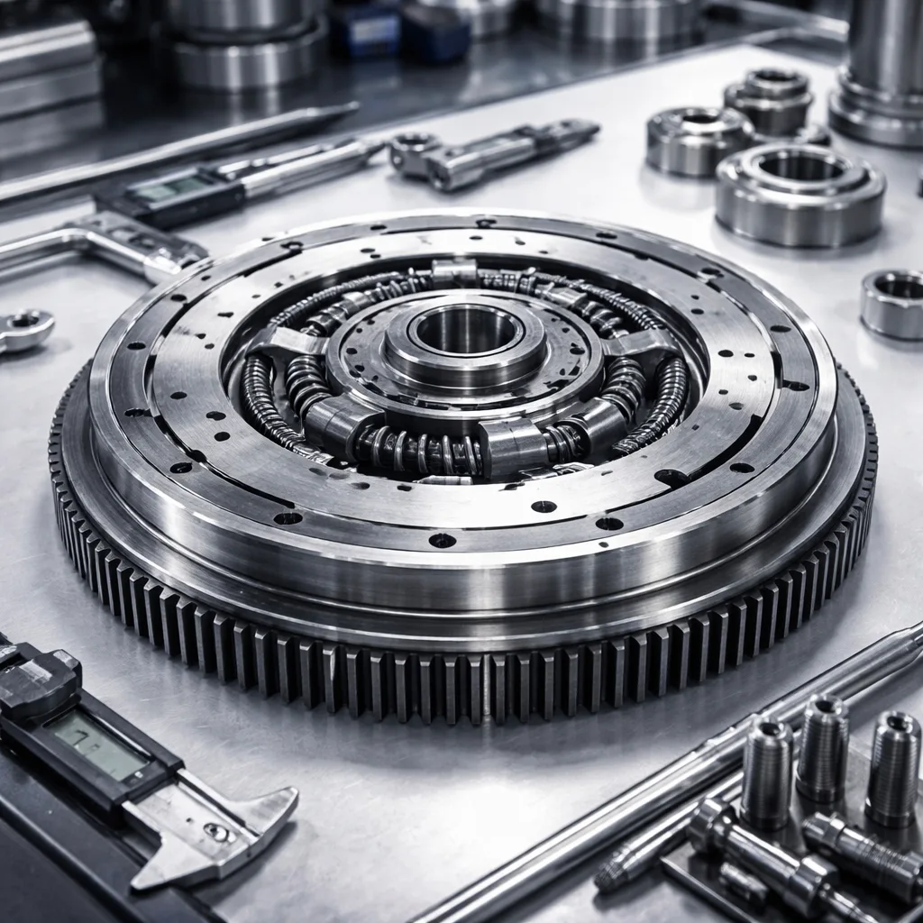
What a flex plate does and when to replace it
A flex plate transfers engine torque from the crankshaft to the torque converter and provides the mounting interface that allows the automatic transmission to receive drive. Unlike a manual flywheel, it is usually thinner and designed with controlled flexibility to accommodate small movement between the engine and converter. On many vehicles, the outer ring gear is also used by the starter motor during cranking.
Failure often develops around stress points: the crankshaft bolt circle, converter mounting pads, welded ring gear area, or any section exposed to heat and vibration. Once a flex plate is cracked or distorted, reuse is not recommended because the defect can spread quickly under cyclic load.
Common replacement triggers
Cracks radiating from the crank flange, converter pad, or lightening holes
Ring gear tooth wear, chipped teeth, or repeated starter engagement noise
Visible runout, often noticed as vibration at idle, during gear engagement, or under light load
Elongated bolt holes, fretting, or shiny movement marks around mounting points
Heat marks after transmission, torque converter, or starter failure
Local bending caused by incorrect converter seating or previous installation damage
If you are sourcing for a workshop chain, fleet maintenance operation, or distributor, replacement should be authorised when inspection shows fatigue, distortion, ring gear damage, or uncertain service history after a major drivetrain failure. Do not straighten and reuse a bent plate, and do not reuse a unit with cracks, overheating, or damaged mounting holes. For procurement planning, compare fitment data and dimensional drawings in our catalog and review the wider engine product range on engine components when consolidating related part families.
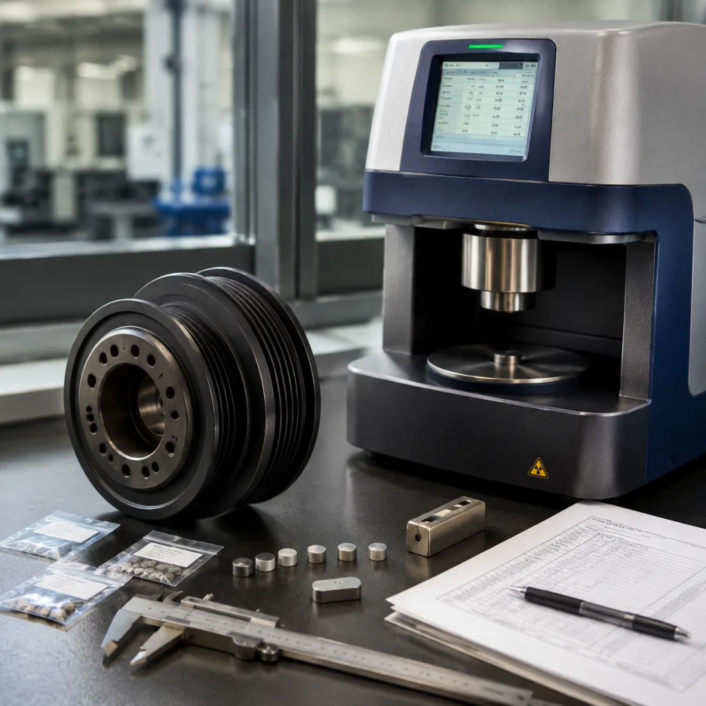
Before you start: fitment and safety checks
A correct repair begins with identification. Confirm the engine code, transmission type, torque converter bolt pattern, outside diameter, offset, crankshaft bolt pattern, and starter ring gear specification before the vehicle is dismantled where possible. If the application uses an OE-style cross-reference such as OE 06A107065, treat that reference as a starting point, not the only confirmation. The exact engine and transmission combination still needs to match.
Check item
What to confirm
Outside diameter
Matches the removed part and has correct bellhousing clearance
Thickness and offset
Consistent with OE design to maintain converter alignment and crank spacing
Crankshaft bolt pattern
Bolt holes align exactly and the centre register seats correctly
Converter bolt circle
Converter pads or mounting holes match the torque converter used on the vehicle
Tooth count / ring gear
Starter engagement matches the original design with no pitch conflict
Material condition
No cracks, deformation, shipping damage, or local heat damage
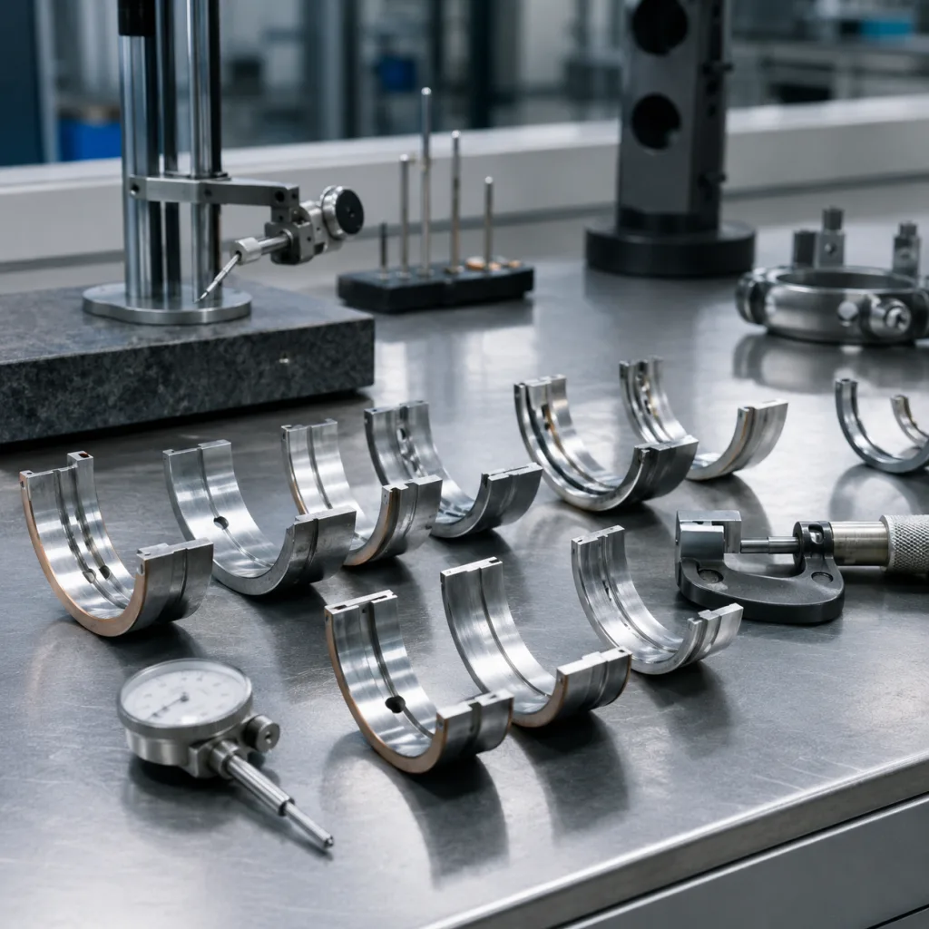
Surface flatness and runout
No visible warp; measure if service equipment is available
Orientation marks
Any dish, spacer, or offset feature is installed in the correct direction
</tr></thead><tbody> </tbody></table>Safety is just as important as fitment. Disconnect the battery, raise and support the vehicle correctly, and keep the transmission fully supported if access requires separation from the engine. A torque converter that slides forward or is not fully seated can damage the pump, flex plate, or fasteners during reassembly.
For fleet or multi-site workshop programmes, create a pre-install inspection record. At minimum, retain the part number, batch code, purchase reference, vehicle application, and installer notes. Driventus supports documentation aligned with IATF 16949:2016 and ISO 9001:2015, and our quality system explains the controls used for incoming material, forming, welding, and final inspection.
Step-by-step replacement procedure
The exact access method depends on the vehicle layout, engine bay packaging, and transmission design, but the working sequence follows the same logic: gain safe access, separate the required components without loading the converter, verify the old and new parts, then torque and validate the assembly.
1. Disconnect power and prepare the vehicle. Remove the battery negative lead, raise the vehicle on approved supports, and make sure there is enough access to remove the starter, inspection cover, or transmission as required. 2. Gain access to the bellhousing area. Depending on the platform, you may need to remove the starter motor, lower inspection cover, exhaust section, driveshaft or axle components, transmission crossmember, wiring brackets, or cooler line supports. 3. Support the transmission and converter. Use the correct lifting equipment. Do not allow the transmission input shaft or torque converter to hang on the flex plate or crankshaft. 4. Mark the converter-to-flex-plate relationship if reused. When practical, record the original converter position. This can help maintain balance relationship on some applications, although service data should always take priority. 5. Remove converter fasteners. Rotate the engine by hand to access each bolt through the service opening. Use the proper tool engagement to avoid rounding the fasteners. 6. Separate the transmission or create the required clearance. Follow the vehicle repair procedure. Ensure the converter stays seated in the transmission and does not move forward unexpectedly. 7. Remove the old flex plate. Loosen crankshaft bolts in a controlled pattern. Inspect the crank flange, dowel or register location, converter pads, ring gear, and surrounding bellhousing area for contact marks. 8. Compare old and new parts side by side. Check diameter, tooth count, offset, crank bolt pattern, converter bolt circle, dish direction, spacer requirements, and ring gear position before installation. 9. Clean the mating surfaces. Remove burrs, dirt, corrosion, and old thread-locking residue. The crank flange and flex plate mounting face must sit flat. 10. Install the replacement part in the correct orientation. Align any dowel, register, or asymmetric bolt pattern. If the vehicle service information specifies new bolts, sealant, thread locker, or a particular washer arrangement, follow it exactly. 11. Torque crankshaft bolts in stages. Use the manufacturer’s published torque values and tightening sequence. Do not estimate torque by feel, and do not substitute values from a different engine family. 12. Re-seat and align the torque converter. Before tightening converter bolts, confirm the converter is fully seated and has the specified movement or pull-up distance. Lack of free play can indicate incorrect seating or part mismatch. 13. Torque converter fasteners separately. Tighten in stages and rotate the assembly by hand between positions. Follow the specified thread-locking method and final torque value. 14. Rotate the complete assembly by hand. Check for binding, scraping, starter ring gear wobble, or interference with the inspection cover or bellhousing before final reassembly. 15. Reassemble removed components. Refit covers, starter, mounts, exhaust sections, wiring retainers, and driveline components according to the repair data.
If the replacement is part of a managed supply programme, include an installation instruction sheet or inspection checklist with each shipment. For special dimensions, non-standard hole patterns, or low-volume applications, custom manufacturing can support application-specific builds based on drawings, samples, or verified fitment data.
Validation after installation
The job is not complete until the assembly has been checked under operating conditions. After reassembly, confirm that the starter engages cleanly and that the engine starts without clash, scraping, or rhythmic knocking. Idle quality should not deteriorate, and there should be no new vibration when shifting from park or neutral into drive or reverse.
Post-install checks
Verify crankshaft and converter fasteners were torqued to the published specifications
Confirm there is no contact between the flex plate, inspection cover, bellhousing, or starter nose
Check starter engagement quality during several crank cycles
Listen for ticking, scraping, knocking, or intermittent metallic contact at idle
Confirm the torque converter and transmission operate normally after fluid level checks where applicable
Road test for vibration under light load, steady cruise, deceleration, and initial take-off
Reinspect after the first heat cycle on commercial-duty, fleet, or high-idle vehicles
If a problem appears after replacement, do not assume the new part is the only cause. Common issues include an incorrectly seated converter, wrong offset, damaged starter drive, missing spacer, reused stretched fasteners, debris between the crank flange and flex plate, or a mismatch in ring gear tooth count. A basic runout check can also help identify installation or component concerns before repeated failures occur.
For fleet buyers, validation should include a short test record: vehicle model, engine and transmission type, part number supplied, batch code, torque values used, technician name or workshop location, and any anomalies found. This record helps reduce repeat claims and supports supplier qualification. If you need replacement stock or a validated part programme, request a quote and include the application details, OE reference, sample availability, and annual volume.
How Driventus supports replacement supply
Driventus supplies flex plates for aftermarket distribution, OEM and Tier-1 supply chains, and multi-location repair networks. For procurement teams, the key requirements are dimensional match, material consistency, stable lot control, and clear fitment communication. A flex plate may appear simple, but small deviations in offset, tooth count, bolt-hole position, or ring gear quality can cause costly returns at workshop level.
Our production and export process is structured for repeatable supply. Key support points include:
Traceable batch control and incoming material verification
Process checks for stamping, forming, welding, heat treatment where applicable, and final inspection
Dimensional review for crank bolt pattern, converter bolt circle, offset, outside diameter, and ring gear position
Packaging suitable for export handling, warehouse storage, and distributor picking operations
Support for OE-style cross-reference listing without claiming vehicle maker approval
Documentation support for sourcing teams, including inspection records and compliance information when required
If your sourcing brief needs a direct replacement programme, send the application data, sample part, OE-style reference, or dimensional drawing. Where required, we can align with REACH (EC) No 1907/2006 expectations for material compliance and support documentation used in regulated markets. For broader sourcing across engine and powertrain parts, start with our catalog and contact our team for a supply review.
Frequently asked questions
Replace it if you find cracks, warping, damaged starter ring gear teeth, elongated bolt holes, fretting, heat marks, or visible runout. A flex plate with structural or mounting damage should not be straightened and reused.
Only if the vehicle repair data allows reuse and the bolts are undamaged. Many applications require new fasteners, a specified thread-locking method, or a defined torque-and-angle procedure, so follow the published service information.
Yes. We can review OE-style references, including OE 06A107065 when applicable, and confirm dimensional match for the correct engine and transmission combination. OE references are used for fitment identification only.
If you are building a replacement supply list or need application confirmation, send the vehicle data, OE-style reference, sample details, and target volume through /contact.html.