Engine Valve How to Replace: Procedure and Checks
Replacing an engine valve is a precision job, not a generic teardown task. The right approach depends on valve type, head material, seat condition, guide wear, and the target application. For procurement teams, the main risk is not only wrong fitment but also poor dimensional control, inconsistent stem finish, or missing validation data from the supplier.
This guide frames the work as a decision process: what to verify first, when replacement is safe, where failures happen, and which measurements should be documented before release. It is written for sourcing engineers, category buyers, and import managers who need repeatable parts and clear technical records. Driventus is an independent aftermarket manufacturer; brand names are referenced for fitment only. Our parts are produced under IATF 16949:2016 and ISO 9001:2015 controls, with material and dimensional verification aligned to customer requirements and relevant regulatory expectations such as REACH (EC) No 1907/2006 where applicable.
First decide whether replacement is enough
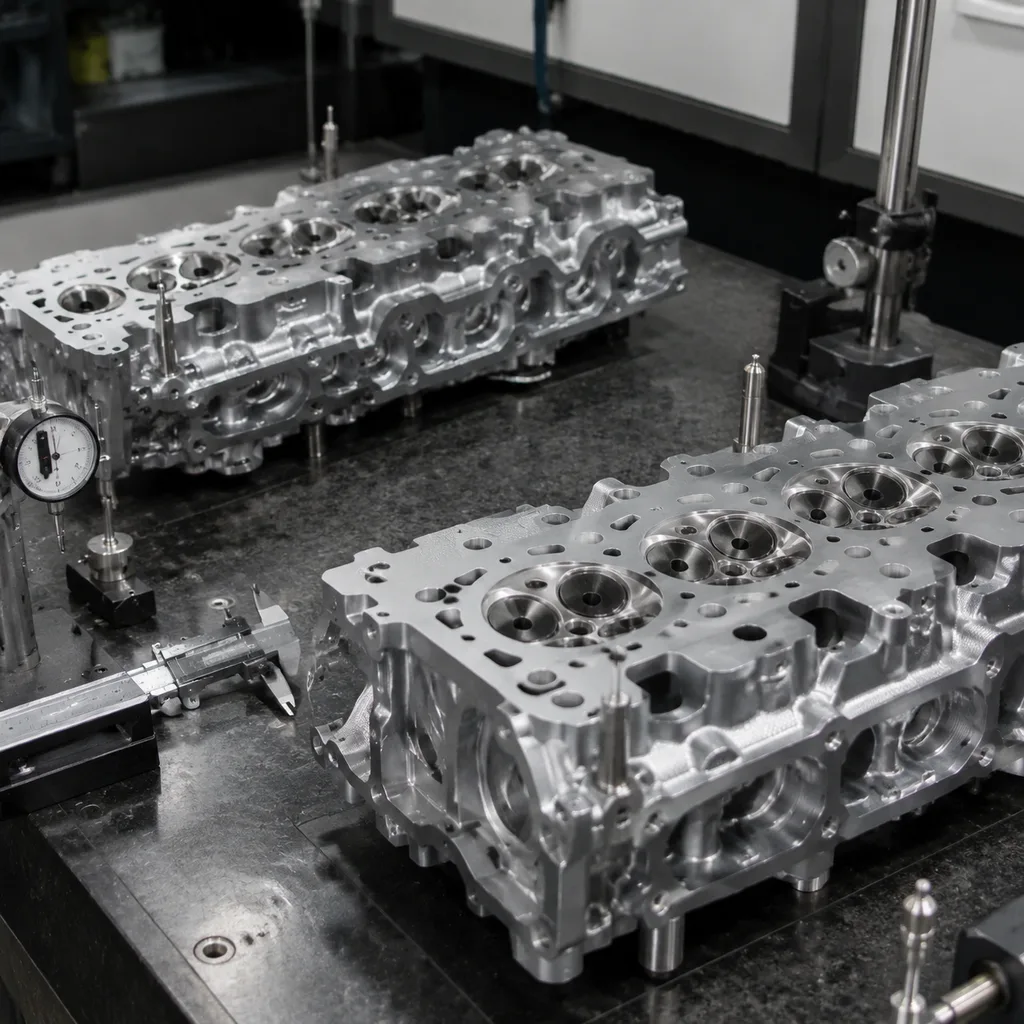
Before any engine valve replacement work begins, confirm the exact application and service condition. Valve geometry must match the head design, combustion chamber shape, installed height, seat width, and the engine’s thermal duty cycle.
Check these points first:
- OE reference, engine code, and cylinder position
- Intake or exhaust valve position
- Head diameter, stem diameter, overall length, and lock groove geometry
- Stem tip hardness and surface finish
- Valve margin thickness, face angle, and backface angle
- Guide clearance, seat concentricity, and installed height target
The key decision is simple: if the guide is worn, the seat is recessed, or the head shows heat damage, a new valve alone will not solve the problem. Ask the supplier to state nominal dimensions and tolerance bands, not just a part number. Common buyer-requested controls include stem diameter within ±0.01 to ±0.02 mm of nominal, overall length within ±0.10 mm, head diameter within ±0.05 to ±0.10 mm, and face angle held to the seat specification, often 45° or 30° depending on the design.
For lead-time planning, standard replacement valves are often stocked on a 7 to 15 day dispatch cycle, while special alloys, private-label packaging, or non-catalog dimensions can extend to 30 to 45 days depending on tooling and finishing steps. Typical MOQs are 50 to 100 pieces for catalog parts and 300 to 500 pieces for custom packs or private-label programs, but buyers should confirm by engine family and packing format. For broader part-family sourcing, see our catalog and engine components.
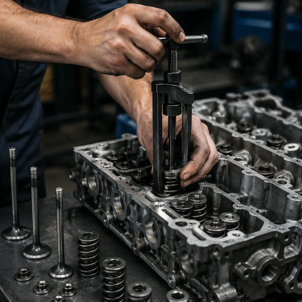
Replacement workflow, stripped to the essentials
Use the service manual for torque values, spring compressor instructions, and head-specific limits. The sequence below applies to most overhead-valve and cylinder-head repairs, but the final acceptance should always reflect the engine manufacturer’s limits.
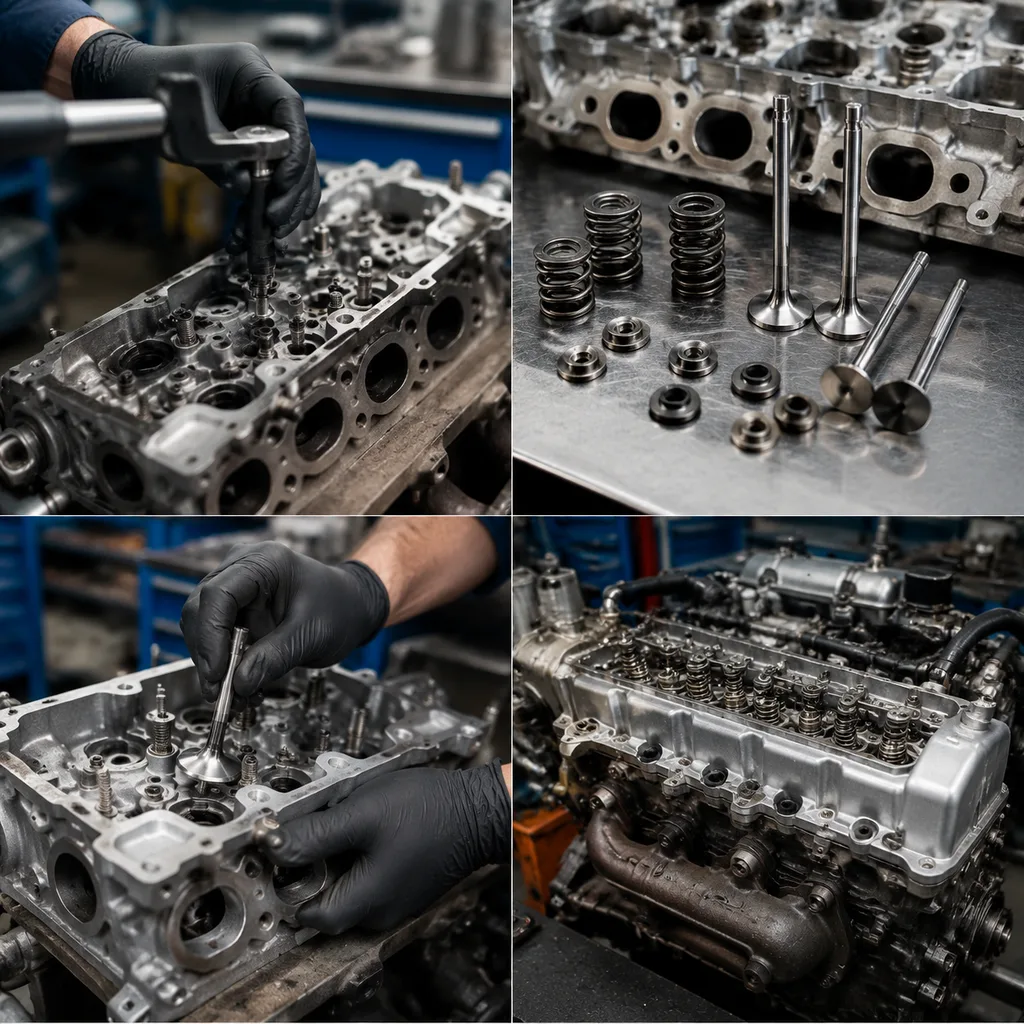
1. Remove the cylinder head and label all valves by cylinder and position so intake and exhaust parts are not mixed. 2. Compress the spring and remove the keepers, retainer, spring, and seal. 3. Withdraw the valve and inspect the stem for scoring, carbon tracks, step wear, and localized heat tint. 4. Clean the guide bore and measure guide-to-stem clearance with a dial bore gauge or comparable method. 5. Lap lightly only if the manufacturer allows it; use only enough compound to show a uniform contact band, typically around 1.5 to 2.0 mm wide for many passenger-vehicle applications. Excessive lapping changes seat contact width and can reduce margin thickness. 6. Install the new valve, then confirm free movement without binding and verify that it drops under its own weight in the guide when appropriate. 7. Fit a new stem seal, spring, retainer, and keepers as required. 8. Verify installed height, spring seat load, and valve protrusion before final assembly.
For process control, many rebuilders target guide-to-stem clearance in the range of about 0.02 to 0.05 mm for intake valves and 0.03 to 0.07 mm for exhaust valves, but the actual limit depends on bore size, material, and engine design. Do not force a valve through a damaged guide. If insertion drag is uneven, the guide may need reaming or replacement before the new part is installed.
Failure modes that shorten valve life
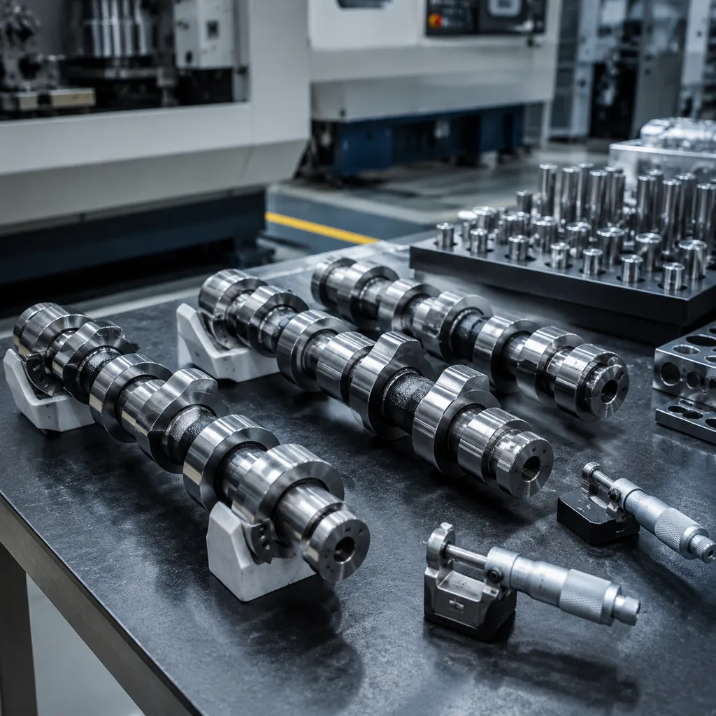
A replacement valve should be validated with the same discipline used in production receiving inspection. Small deviations can affect sealing, heat transfer, and durability, so buyers should require measurable acceptance criteria rather than visual-only approval.
| Check item | Typical control point | Why it matters |
|---|---|---|
| Stem diameter | Match to guide spec, often within ±0.01 to ±0.02 mm | Controls oil consumption and side loading |
| Head diameter | Match OE or approved alternate, typically within ±0.05 to ±0.10 mm | Preserves airflow and seat contact |
| Face angle | Match seat angle, commonly 30° or 45° | Ensures full ring contact |
| Total length | Within engine tolerance, often ±0.10 mm | Maintains installed height |
| Runout | Low measured deviation, frequently ≤0.02 mm on precision parts | Reduces leakage and hot spots |
| Surface finish | Smooth stem finish, often Ra 0.2 to 0.4 µm | Lowers guide wear |
| Hardness | Must meet specified range by location and alloy | Protects tip, stem, and face life |