Engine Bearing Audi OEM Supplier: Sourcing Criteria
When evaluating an engine bearing audi oem supplier, price should come after the fundamentals: fitment control, bearing construction, process capability, and shipment traceability. Buyers need confidence that shell geometry is repeatable, steel-backed bi-metal or tri-metal metallurgy is stable, overlays or polymer coatings are controlled, export packaging prevents corrosion, and documentation can stand up to customer or regulatory review.
For engine bearings used in Audi applications, the usual approval checks include shell wall thickness, installed crush, eccentricity, bearing width, oil-hole and groove alignment, locating tang geometry, surface roughness, overlay condition, oil-clearance calculation, thrust face geometry where relevant, and the exact OE cross-reference before any sample is released into a trial order. Driventus is an independent aftermarket manufacturer; brand names are referenced for fitment only. We support B2B programmes for distributors, wholesalers, Tier-1 suppliers, engine rebuilders, and repair networks with export-ready packing, batch traceability, and technical data aligned to IATF 16949:2016 and ISO 9001:2015.
This guide outlines what to confirm before moving from enquiry to sample, and from sample to repeat order. It is written for buyers who need dependable supply, controlled substitution risk, and clear sourcing criteria rather than broad catalogue claims.
What buyers should verify first
A credible engine bearing audi oem supplier should be able to confirm three points before a serious quotation: the engine family, the bearing position, and the exact size class. Main bearings, conrod bearings, thrust washers, and flanged thrust bearings are not interchangeable, even when the engine code, catalogue note, or model-year range appears to match. Small differences in crankshaft journal diameter, housing bore, bearing width, locating tang position, oil groove layout, and thrust face design can determine whether the part builds correctly or creates warranty exposure.
Begin with the OE reference, then confirm whether the request is for standard size, crankshaft undersize, or housing oversize parts. In rebuild markets, common crankshaft repair increments include 0.25 mm and 0.50 mm undersize, with other increments used depending on engine family and regional practice. The RFQ should state the required size class clearly rather than relying on a loose description such as “STD” or “repair size.” If the application uses a service kit, ask whether the kit includes matched upper and lower shells, thrust pieces, or only the bearing set. Also confirm whether the buyer needs one complete engine set, a pair set, or individual shells packed for workshop replacement.
For buyers managing several warehouses, it helps to align the request with our catalog and, where needed, the broader engine components range. That reduces duplicate enquiries and keeps purchasing, quality, and warehouse teams working from the same controlled reference list.
A practical RFQ should include:
- OE cross-reference and engine code
- Vehicle platform, production year range, fuel type, and destination market where available
- Bearing position: main, conrod, thrust washer, or flanged thrust bearing
- Standard, undersize, or oversize class, with requested repair increment in mm or inch
- Quantity per engine set, shell count, and whether upper/lower shells differ
- Packing unit required: individual shell, pair, cylinder set, or full engine set
- Target annual volume and forecast split by part number and repair size
- Packaging format, barcode standard, inner-box count, carton label fields, and pallet limits
- Destination market and compliance documents required
- Any approved sample, drawing, crankshaft journal data, or previous supplier reference used for comparison
Before sample approval, ask the supplier to confirm the full fitment logic in writing. A low-price quotation is not useful if the buyer later discovers that bearing position, repair size, oil-groove configuration, or kit content was interpreted differently.
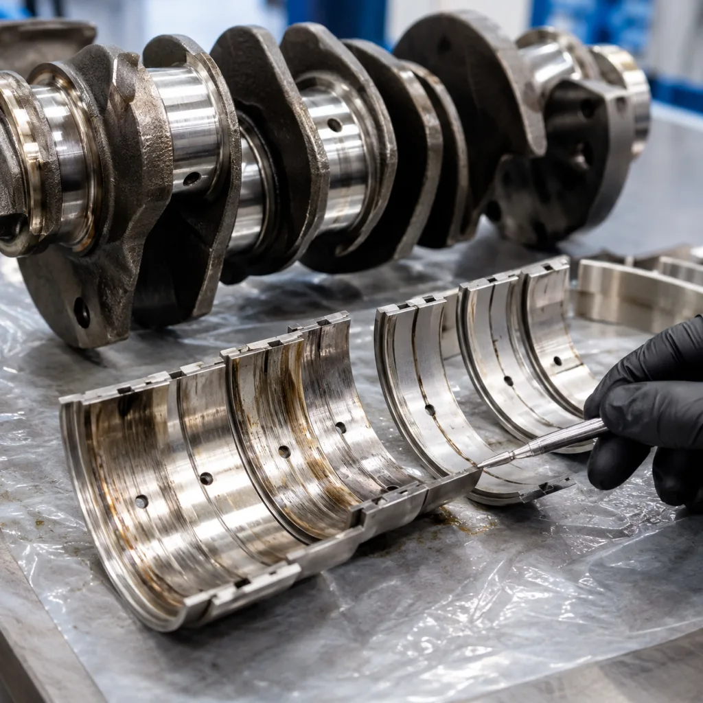
Dimensional control and bearing build
Engine bearings are judged first by geometry, then by surface finish and material integrity. A supplier that only quotes part numbers is not giving enough technical signal. Buyers should ask for a first-article inspection report covering wall thickness, half-shell height, installed crush, eccentricity, width, locating tang position, oil-hole alignment where applicable, groove profile, thrust face geometry, and coating or overlay specification.
The reason is straightforward: engine bearing performance depends on a controlled hydrodynamic oil film under load. If wall thickness varies, oil clearance can move outside the intended range. In many passenger-car engine bearing applications, radial oil clearance is controlled in the tens of microns, so even small shell-thickness drift can affect noise, oil pressure, and seizure margin. Weak crush can allow the shell to lose seating force in the housing bore. Poor eccentricity control can prevent the bearing from creating the expected oil wedge and side leakage pattern. An inconsistent overlay may lead to premature wear, wiping, fatigue cracking, or seizure under boundary-lubrication conditions.
| Checkpoint | What to confirm | Why it matters |
|---|---|---|
| Backing steel | Steel grade, strip thickness, hardness range, and forming stability | Controls load capacity, heat transfer, and housing fit |
| Intermediate layer | Aluminium-tin alloy, copper-lead layer, nickel barrier, or specified equivalent | Determines fatigue resistance, conformability, and compatibility with the engine duty cycle |
| Overlay system | Material type, nominal thickness, thickness variation, adhesion, and surface condition | Affects seizure resistance, embedability, and wear behaviour |
| Optional coating | Polymer or low-friction coating type, cured thickness, adhesion, and coverage | Supports start-stop, dry-start, and mixed-lubrication durability where specified |
| Wall thickness | Measured at defined crown and offset points with calibrated micrometer or air gauge | Protects calculated oil clearance consistency across lots |
| Crush and free spread | Recorded against the approved drawing or controlled sample | Prevents shell movement, fretting, and loss of seating force |
| Eccentricity | Profile measured across the bearing arc, not only at one point | Reduces edge loading and supports correct oil-film formation |
| Width and side relief | Confirmed against crankshaft fillet radius and housing requirements | Helps avoid interference and supports correct oil distribution |
| Oil holes and grooves | Position, diameter, groove profile, deburring, and breakthrough condition | Maintains lubrication flow and prevents assembly scoring |
| Surface finish | Ra/Rz target where specified; free from scoring, pits, burrs, stains, or flaking | Supports initial lubrication and controlled break-in |
| Package integrity | VCI, tray, separator, sealed bag, or box protection | Avoids corrosion and handling damage in transit |