Connecting Rod for Ford Escape Replacement Sourcing
A connecting rod for Ford Escape replacement programme should start with the engine, not the badge on the tailgate. Escape applications vary by year, region, displacement, fuel system, and engine family, so a rod that looks close on the bench can still create bearing crush, pin-fit, or balance problems during assembly. The approval file needs hard data: crank journal size, piston pin diameter, centre-to-centre length, big-end bore after torque, cap design, bolt specification, side-face width, and matched-set weight limits.
The bigger sourcing risk is not simply “will it fit?” It is whether every batch keeps the same metallurgy, bore geometry, heat-treatment result, fastener quality, cleaning standard, and traceability once the part enters distributor stock or a repair-chain workflow. A practical RFQ should include engine code, sample or drawing, target annual volume, inspection level, packaging format, labelling needs, and lead-time window. For most passenger SUV rods, critical dimensions are commonly controlled in the 0.005–0.020 mm range, while geometry and weight matching must be agreed before tooling, sampling, or batch release.
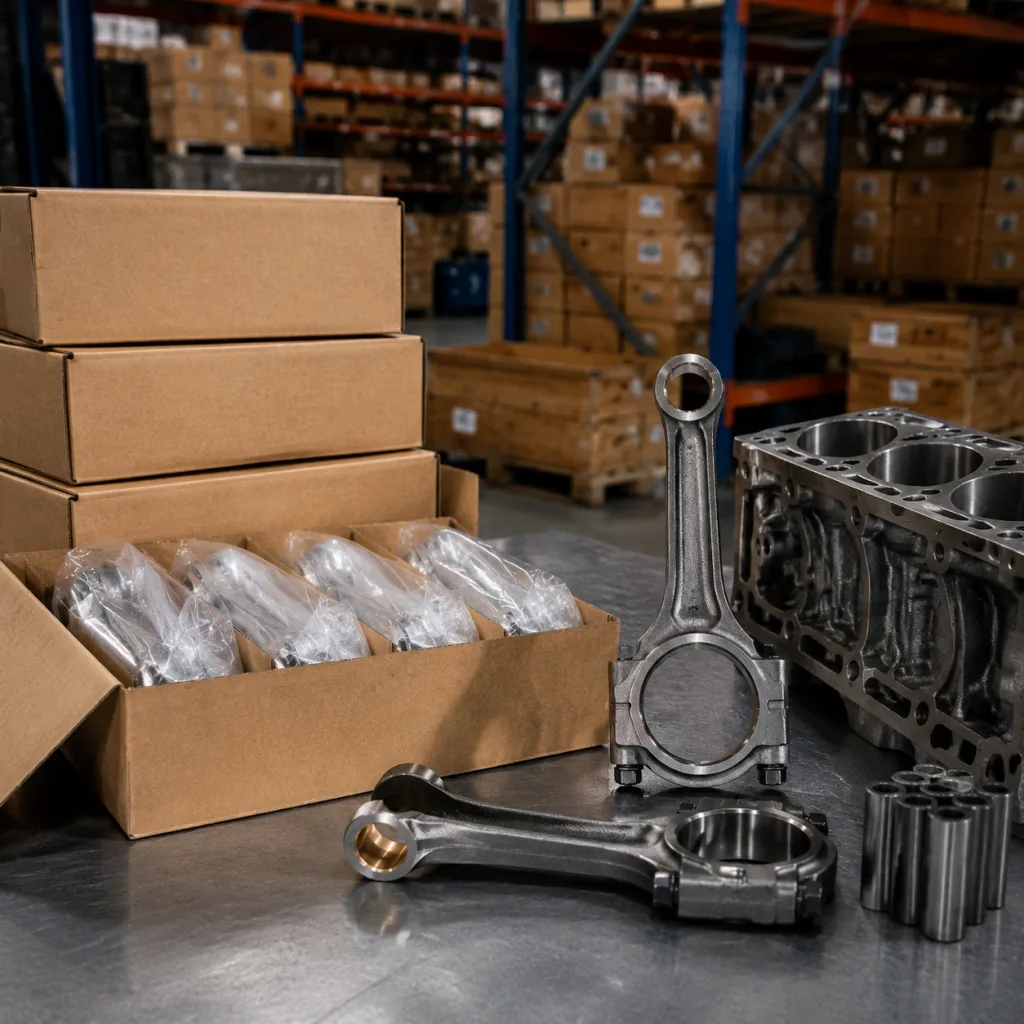
Driventus supplies replacement connecting rods for aftermarket distributors, engine rebuilders, and repair-chain sourcing teams that need controlled production, documented inspection, stable packaging, and repeatable export supply. This article explains how to specify, validate, document, and buy Ford Escape connecting rods without relying on generic catalogue assumptions. Driventus is an independent aftermarket manufacturer; Ford and other brand names are referenced for fitment identification only.
Start With the Engine Code, Not the Vehicle Name
Ford Escape rods should be sourced from a fitment file, not from a broad vehicle title. One model name may cover multiple engine generations, regional calibrations, fuel systems, and production changes. The first decision is therefore simple: can the supplier prove the rod matches the exact engine architecture?
A reliable fitment file combines sample parts, engine application lists, dimensional drawings, and any OE part-number cross-references used inside the buyer’s catalogue. Generic references such as OE 06A… or OE 11251… may help catalogue mapping, but they should not replace sample matching, engine-code confirmation, or drawing approval.
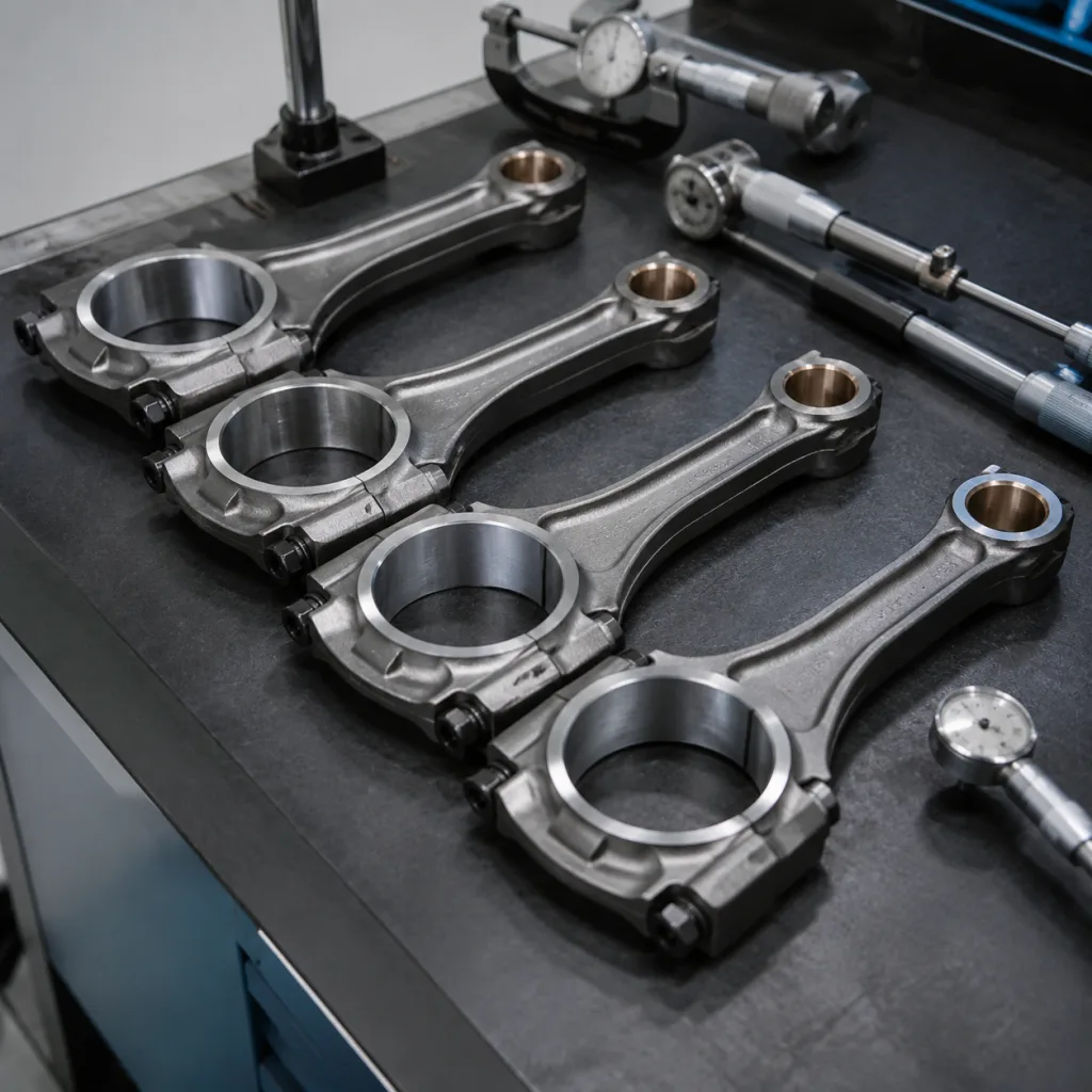
For a connecting rod for Ford Escape replacement order, lock these points before quoting volume:
- Big-end finished bore diameter after cap assembly and final honing, often held to ±0.005–0.010 mm where bearing stability is critical
- Big-end roundness and cylindricity, commonly targeted at ≤0.006–0.010 mm after bolt tightening
- Small-end bore or bush internal diameter after finish machining, typically controlled to ±0.006–0.012 mm depending on floating or press-fit pin design
- Centre-to-centre length across one engine set, often specified within ±0.015–0.030 mm from the approved drawing value
- Cap split type, bolt grade, thread pitch, seating face, lubricant condition, and tightening method
- Rod weight range and set-matching method, such as total rod weight within 2–4 g and end-to-end balance within 1–2 g when requested
- Bearing locating tang geometry, side-face width, and crankshaft side-clearance interface
- Piston pin retention system compatibility, including circlip, floating pin, or press-fit configuration
- Surface finish on bearing and pin contact areas, commonly Ra 0.2–0.8 µm depending on the surface function
The approval drawing should also state datum points, bolt condition during measurement, big-end bore size after final honing, small-end bush status, oil-hole position, side-face width, and measuring temperature, typically 20 ±2 °C. Replacement rods should not be described as vehicle manufacturer approved unless formal approval exists. Driventus does not claim such approval; the sourcing objective is OE-equivalent function, dimensional compatibility, and stable aftermarket performance for the defined application.
Where Replacement Rod Programmes Usually Fail
Most connecting rod problems do not start with a dramatic fracture. They start smaller: a bore that moves after bolt tightening, a cap that does not seat repeatably, a bush that is finished slightly tight, or a weight spread that causes vibration complaints after installation. Those issues are expensive because they are often discovered after machining, packing, shipping, warehousing, or engine assembly.
Construction must follow the original strength and clamp-load logic. Passenger-car rods may use forged steel, sintered steel, or powder-metal blanks. If the original rod is fracture-split, replacing it with a machined-cap forged design is not a simple commercial substitution; bearing crush, bolt load, mass, and fatigue behaviour must be reviewed.
| Failure mode | Why it matters | Procurement control |
|---|---|---|
| Unapproved material substitution | Changes fatigue strength, hardness response, and fracture behaviour | Mill certificate plus PMI or spectrometer check |
| Incorrect heat-treatment range | Can reduce toughness or bore stability | Rockwell or Brinell hardness test by batch |
| Big-end bore drift | Causes bearing clearance or crush problems | Air gauge or calibrated bore gauge after cap torque |
| Roundness or cylindricity error | Creates bearing edge loading and oil-film instability | Bore gauge, air gauge, or CMM inspection |
| Centre-distance variation | Affects compression height, piston travel, and engine balance | CMM or dedicated fixture measurement |
| Parallelism or twist error | Can cause piston noise and uneven bearing wear | Rod alignment gauge or CMM |
| Burrs, dents, cracks, or grinding burns | Creates stress risers and assembly defects | Visual and magnetic particle inspection where applicable |
| Poor bolt control | Reduces clamp load consistency | Thread gauge, torque-angle check, proof-load validation |
| Loose weight control | Increases vibration risk across a matched set | Calibrated balance scale with end-weight fixture |
| Document | What it proves for the buyer |
|---|---|
| Dimensional inspection report | Critical bores, centre distance, parallelism, twist, side width, and weight were checked |
| Material certificate | The production batch links to the specified material heat or powder-metal lot |
| Heat-treatment record | Hardness range, furnace batch, and process consistency are recorded |
| Surface inspection record | Crack, burr, dent, and machining-defect screening was performed |
| Fastener inspection record | Bolt specification, thread, coating, proof load, and tightening control are confirmed |
| Packing list with batch codes | Warehouse, shipment, and warranty traceability can be maintained |
| Control plan summary | Recurring production controls and critical characteristics are visible |
| Sample approval record | Master sample, drawing revision, and buyer sign-off date are documented |