Connecting Rod for Citroen Jumper Aftermarket Replacement
Published 2026-06-17. A connecting rod for Citroen Jumper aftermarket replacement is not a van-name purchase. It is an engine-geometry purchase. The quote should start with engine family, production range, crankpin diameter, piston pin diameter, centre-to-centre length, big-end housing bore, big-end width, bearing layout, cap design, bolt specification, and weight group. For importers, wholesalers, and repair-chain procurement teams, the risk is not only fitment. The rod has to keep bore geometry under load, maintain bearing crush, resist fatigue, and remain traceable when the same SKU is reordered months later. A practical RFQ includes measured samples or drawings, target annual volume, destination market, packaging format, tolerance bands, sample approval route, and documentation level. Driventus manufactures engine components in Taizhou, Zhejiang, for B2B customers in more than 60 countries. This article explains how to specify, validate, catalogue, and source replacement connecting rods for Citroen Jumper applications without implying vehicle-maker approval. Driventus is an independent aftermarket manufacturer; brand names are referenced for fitment identification only.
Start with the fitment decision, not the vehicle name
The first decision is whether the requested rod is dimensionally equivalent to the original service part for the stated engine code, displacement, power rating, emissions generation, and production range. A Citroen Jumper model listing is only a starting clue. It is not enough for release.
A strong RFQ identifies the engine and the evidence behind the interchange. Useful inputs include fuel type, model year range, market notes, transmission notes where relevant, and any OE cross-reference already used in the buyer’s catalog system. Driventus can compare these inputs against sample measurements, technical drawings, or buyer-approved references before quotation.
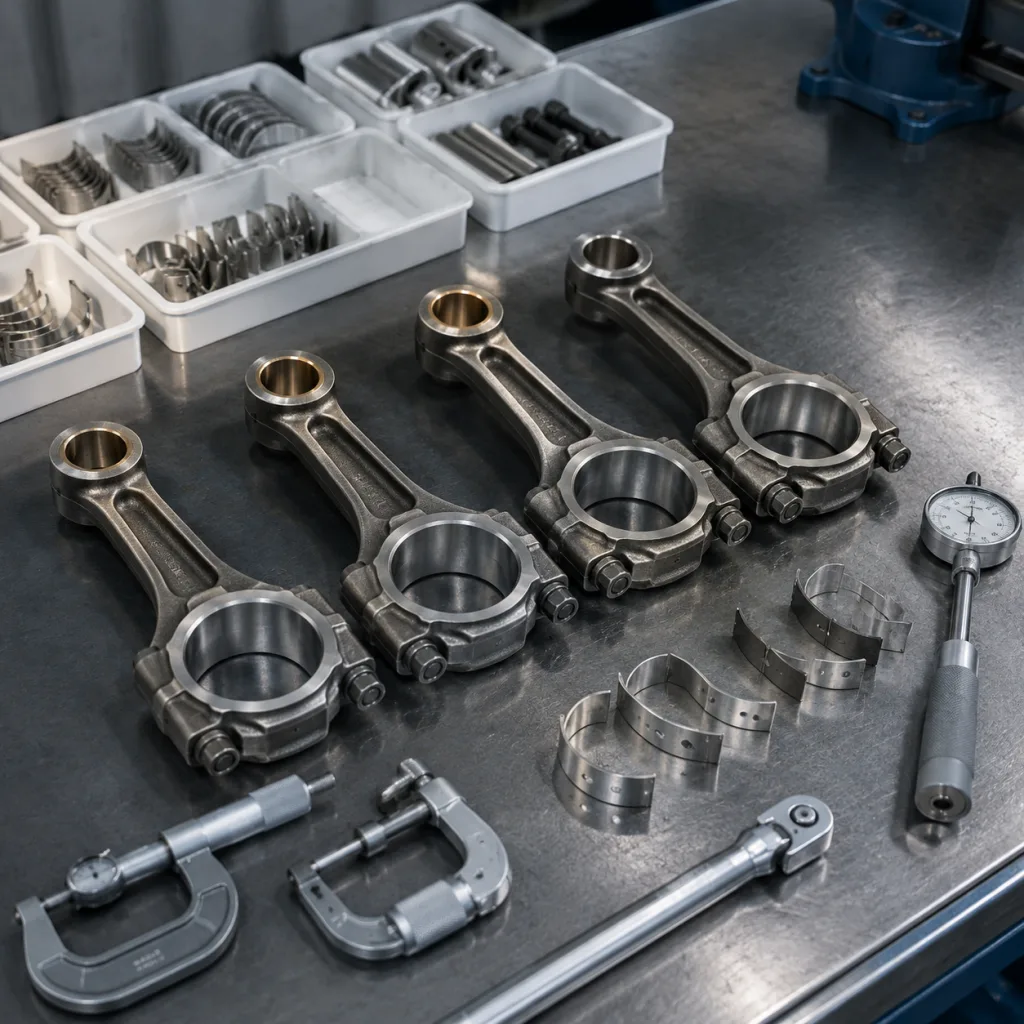
Separate nominal dimensions from tolerances. If no engineering drawing is available, measure at least 3–5 undamaged sample rods from the same application. Clean them first. Install the cap. Tighten the bolts to the agreed torque or torque-angle condition. Then measure bores at 0°/90° and at both edge and centre positions so wear, ovality, and production scatter are not mistaken for design intent.
Critical dimensions normally include:
- Centre-to-centre length between big-end and small-end bores; many drawings control this within about ±0.02–0.05 mm depending on design and inspection method
- Big-end housing bore diameter after cap assembly and torque simulation; size, roundness, and taper need bore-gauge or air-gauge inspection, not caliper estimates
- Crankpin journal diameter and compatible bearing shell specification, including shell width and locating tang position where applicable
- Small-end bore diameter, with or without bushing depending on design; bushed bores should be checked after pressing and final reaming or honing
- Big-end width and side-clearance target; a 0.10 mm width error can matter in some crankshaft assemblies
- Piston pin diameter, bushing oil-hole alignment, and chamfer profile to avoid pin-edge loading
- Bolt size, thread form, grade, under-head radius, seating face, tightening method, and whether replacement bolts are mandatory
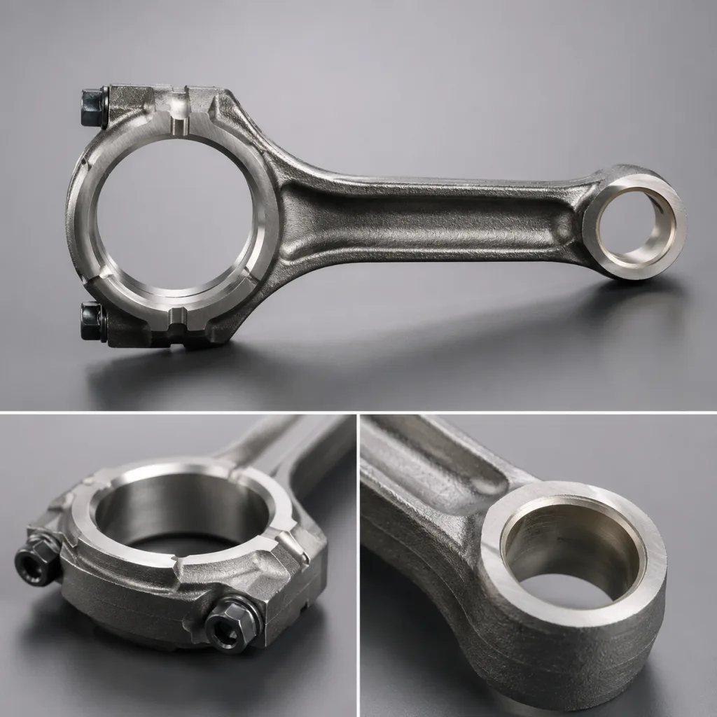
- Parting-face type, including machined or fracture-split construction; fracture-split caps must remain paired and orientation-controlled
- Weight per rod and weight group for single-piece supply, engine sets, or matched overhaul kits
The common failure in purchasing is assuming that platform sharing means part sharing. Citroen Jumper vehicles may share engine families with other European light commercial vans, but rod geometry can change by displacement, emissions generation, piston compression height, crankshaft specification, bearing design, and production year. A catalog entry that fits one engine version can be wrong for another if the big-end width, pin size, bolt seat, or cap design changes.
For this reason, procurement specifications should reference engine identifiers and measured samples rather than relying only on vehicle listings. Related engine parts can be reviewed in our catalog, including the engine component range at /products/engine-components.html.
Where replacement rods usually fail in production
Most connecting-rod problems do not begin with the headline material name. They begin with mismatched process assumptions: wrong heat-treatment window, bore movement after bolt preload, cap mix-up, poor bushing alignment, loose weight sorting, or undocumented bolt changes. For diesel light commercial vehicles, forged steel and powder-forged steel are both used. The right route depends on the load case, drawing requirement, fatigue target, and production economics.
If the buyer already has a validated reference part, material selection should be matched by chemistry, hardness, microstructure expectation, weight, and machining behavior rather than by a generic steel label. Driventus confirms the material route with the customer before tooling, sampling, or mass production.
| Failure mode to prevent | Control point | Practical acceptance detail |
|---|---|---|
| Fatigue risk from wrong material route | Forged or powder-forged steel per approved drawing | Confirm steel grade, billet or powder route, supplier approval, and heat number traceability |
| Hardness drift after thermal processing | Controlled quench and temper or equivalent approved process | Record furnace batch, cycle parameters, and load position where required |
| Unstable bearing crush | Big-end bore roundness after cap assembly and tightening | Check with bore gauge or air gauge at multiple clock positions; caliper checks are not sufficient |
| Pin-edge loading or oil starvation | Small-end bushing fit and oil-hole position | Confirm interference, oil-hole alignment, final bore size, and surface finish |
| Installer complaints during rebuilds | Weight grouping | Agree a realistic band; common aftermarket groups may use ±2–5 g, while tighter bands add sorting cost |
| Bearing or thrust-face wear | Surface finish | Verify bore and thrust-face finish to drawing, normally by Ra value where specified |
| Clamp-load variation | Bolt grade, coating, thread, and tightening method | Torque-only and torque-angle systems are not interchangeable without validation |
| Area | Questions to confirm |
|---|---|
| Technical data | Are drawings, samples, or approved measurement reports available, and are critical dimensions toleranced? |
| Fitment release | Is the application tied to engine code, production range, and measured geometry rather than model name only? |
| Process control | Is cap matching, bolt tightening, bore honing, washing, rust prevention, and final inspection documented? |
| Quality management | Is the facility certified to IATF 16949:2016 and ISO 9001:2015, and can audit evidence be provided? |
| Traceability | Can batches be linked to material heat, heat treatment, machining date, inspection record, and packing lot? |
| Packaging | Are rods protected against corrosion, cap mix-up, thread damage, and carton collapse during ocean freight? |
| Change control | Will the supplier notify changes to material, tooling, machining route, coating, bolts, or sub-suppliers? |
| Commercial terms | Are MOQ, sample timing, lead time, payment terms, incoterms, and repeat-order capacity agreed in writing? |