Carbon Buildup on Intake Valves: Valve Stem Seal Checks
Carbon buildup on intake valves usually points to oil entering the intake stream, combustion control that is out of balance, or service intervals that allow deposits to accumulate beyond the engine’s self-cleaning range. For procurement teams and remanufacturers, the key question is not only what is dirty, but which failure mode is driving repeat claims. Valve stem seals are one of the first components to inspect because they regulate oil flow along the valve guide during intake and exhaust cycles. When a seal hardens, shrinks, or loses lip tension, oil can migrate into the port and leave wet, carbon-rich deposits on the back of the valve. In many warranty returns, the pattern is most visible after 60,000–120,000 km of mixed-use operation, especially on engines with extended idle time or heavy heat cycling. Driventus is an independent aftermarket manufacturer; brand names are referenced for fitment only. This article explains symptom patterns, inspection points, and sourcing criteria for replacement seals used in high-volume engine work. For product families and OEM-reference coverage, see [our catalog](/products.html), [quality system](/quality.html), [custom manufacturing](/oem-services.html), and [request a quote](/contact.html).
What carbon on intake valves usually means
Intake-valve deposits rarely come from a single fault. In fleet and workshop data, the most common triggers are:
- Oil passing a worn or hardened valve stem seal
- Excessive guide clearance that overloads the seal lip
- PCV system faults that increase oil vapour ingestion
- Misfire, rich running, or low-temperature operation that slows burn-off
- Long drain intervals and fuel dilution that accelerate deposit formation
A failed seal does not always create an obvious smoke complaint. Many engines show only rough cold idle, higher misfire counts, or uneven airflow between cylinders. On direct-injection engines, deposits can be more visible because fuel no longer washes the intake valve face. In practice, technicians often see deposits first on cylinders with intake vacuum variance above about 2–3 kPa at idle, or on engines that have spent long periods below full operating temperature. That makes seal condition especially important in diagnosis when repeat carbon complaints appear after cleaning.
How valve stem seals affect deposit formation
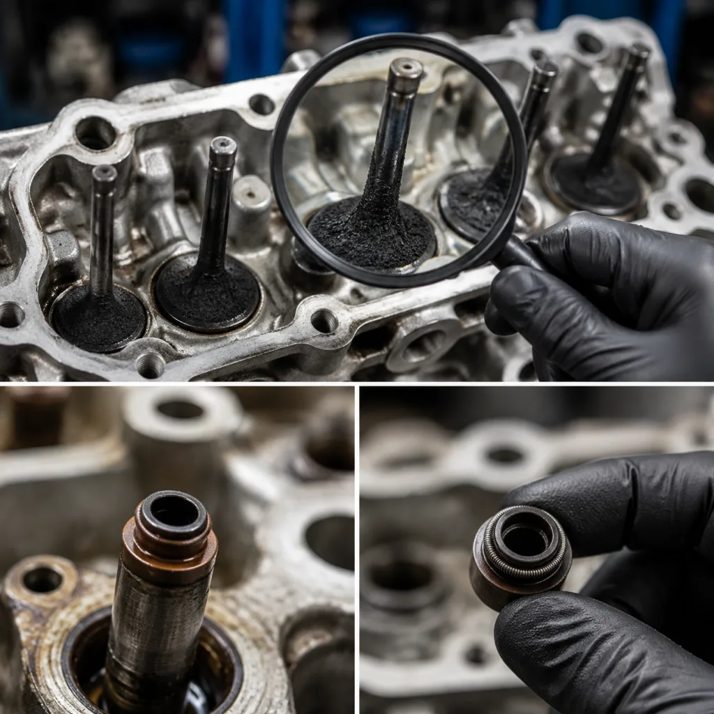
A valve stem seal meters a very small oil film needed for guide lubrication. If the seal loses elasticity, the oil-control function becomes inconsistent. The result is not only oil loss, but coking on the valve stem, the guide top, and the back of the valve.
Failure pattern
- Hardened rubber or fluoroelastomer lip
- Heat cracking after prolonged high-load use
- Loss of interference fit on the guide
- Stem wear that prevents proper wiping action
- Spring retainer contamination that reduces seal contact
Deposits from seal leakage often appear as sticky black varnish near the stem top and heavier carbon on the valve head. If one cylinder is worse than the others, guide wear or a local sealing issue is more likely than a broad combustion problem. A practical shop check is to compare the installed seal height and stem-to-guide condition across all cylinders; a deviation of more than 0.1–0.2 mm in installed height or a noticeable difference in stem oil film often tracks with the worst deposit cylinder. For buyers, the important point is that the carbon buildup intake valves valve stem seal issue is usually a system problem, not a single-part problem.
Inspection steps before replacement
Before ordering replacement parts, confirm the root cause with a simple sequence:
1. Check compression and leak-down to rule out ring or valve seating faults. 2. Inspect the PCV system for restriction, excessive vacuum, or oil carryover. 3. Remove the intake manifold if needed and photograph valve back faces by cylinder. 4. Measure valve stem diameter, guide clearance, and installed seal height. 5. Look for blue smoke after deceleration and extended idle, which can indicate oil-control loss. 6. Verify whether the engine uses positive-stop, umbrella, or integrated seal designs.
Use measurable acceptance points, not visual judgment alone. Typical workshop references are stem-to-guide clearance around 0.03–0.06 mm on light-duty gasoline engines and roughly 0.05–0.10 mm on many higher-mileage or larger-displacement applications, but the OE spec always controls. If stem wear is present, measure with a micrometer at more than one point on the stem; taper or out-of-round above 0.01–0.02 mm can reduce seal wipe performance. If the seal lip is intact but guide clearance is outside specification, a seal-only repair may fail early. Procurement teams should treat guide condition, stem finish, and seal material as a matched system.
Replacement criteria for B2B buyers
For distributors, rebuilders, and multi-site repair networks, the priority is dimensional consistency and material compatibility. A replacement seal should match OE geometry, installation load, and heat resistance. Driventus supplies seals built under `IATF 16949:2016` and `ISO 9001:2015` systems, with material control aligned to export-market expectations.
| Check item | What to verify | Why it matters |
|---|---|---|
| Inner lip diameter | Matches stem size and surface finish | Controls oil film |
| Outer body fit | Matches guide bore tolerance | Prevents walk-out or leakage |
| Material | FKM, NBR, or specified elastomer | Heat and oil resistance |
| Spring type | Presence and preload | Maintains wipe pressure |
| Installed height | Within engine assembly spec | Avoids coil bind or seal damage |
| Packaging traceability | Lot code and batch control | Supports warranty tracking |