A camshaft Mercedes-Benz aftermarket replacement is a risk-managed sourcing decision, not a catalogue exercise. The shaft has to match the engine’s functional envelope: lobe geometry, journal finish, phasing interface, oil routing, thrust control, sensor features, hardness, and packaging protection. If one of those details is wrong, the part may install but still trigger timing faults, poor idle, lubrication damage, or early wear.
For distributors, repair networks, and importers, the practical question is simple: can this supplier repeat the same controlled part across samples, pilot orders, and bulk shipments without implying vehicle manufacturer approval? This article gives procurement teams a sharper way to evaluate replacement camshaft programmes for stock ranges, private-label supply, and repair-chain use. It covers the buy/no-buy criteria, dimensional and material checks, validation evidence, supplier controls, failure modes, MOQ logic, and RFQ inputs.
Driventus manufactures engine and powertrain components in Taizhou, Zhejiang, and exports to more than 60 countries under IATF 16949:2016 and ISO 9001:2015 systems. Driventus is an independent aftermarket manufacturer; brand names are used only to identify fitment.
Start with the buy/no-buy question
The first decision is not whether the camshaft looks similar. It is whether the proposed part can reproduce the required function in the target engine.
A Mercedes-Benz fitment camshaft must control valve lift, duration, phasing, journal support, thrust location, lubrication, sensor synchronisation, and any phaser or actuator interface. Procurement specifications should therefore be written around measurable features, not brand-led wording or catalogue assumptions.
For replacement programmes, the goal is OE-equivalent fit, form, and function in the intended application. That means the part must seat correctly in the cylinder head, work with the specified followers or hydraulic lifters, maintain oil flow at operating temperature, and hold timing accuracy through the expected service interval. A useful RFQ defines nominal lobe lift, journal diameter, overall length, bank position, timing slot or reluctor angle, thrust-face width, oil-hole diameter, and cam phaser or actuator interface where relevant.
Use vehicle application data, engine code, year range, fuel type, valve-train layout, camshaft position, and buyer-supplied OE-style cross-references as sourcing inputs. If an internal reference is needed, use a generic convention such as OE 06A107065 only when it already exists in the buyer’s programme data. Do not infer, alter, or create brand-owned part numbers.
A launch file should separate must-match engineering features from catalogue description. Intake and exhaust shafts may share similar length and casting appearance yet differ by trigger angle, lobe centreline, oil groove, or phaser mounting detail. Mixing them can cause misfire codes, poor idle, loss of power, or mechanical interference even when the shaft physically installs.
Driventus lists relevant engine components in our catalog, including camshafts and related powertrain parts. Application fitment should always be confirmed against the buyer’s data before tooling, sampling, or bulk release.
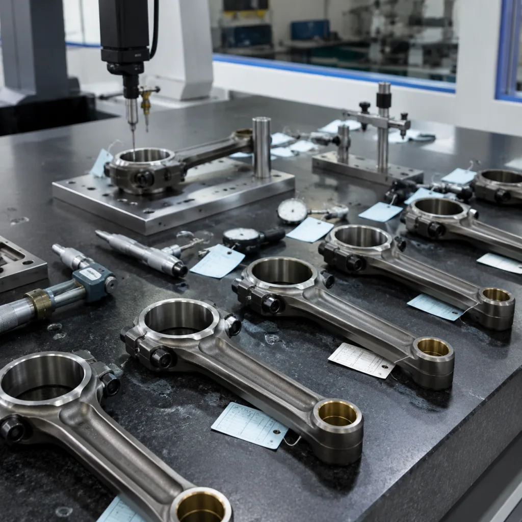
The spec details that decide interchangeability
Camshaft interchangeability is decided by a narrow set of controlled features. A shaft can pass a visual check and still fail because lobe taper, journal runout, thrust-face width, oil-hole location, or timing-feature position is outside tolerance. Ask for drawing tolerances and inspection methods, not only catalogue fitment.
Control item
Typical procurement check
Practical target to define in RFQ
Overall length
CMM or height gauge verification
Nominal length with ±0.10–0.20 mm tolerance unless drawing states tighter
Journal diameter
Micrometre at 3 sections and 2 clock positions
Bearing-clearance driven; often held within ±0.01–0.02 mm
Journal roundness and taper
Roundness tester or precision V-block method
Roundness and taper commonly ≤0.005–0.010 mm
Lobe lift profile
Cam profile measuring machine
Lift tolerance often ±0.03–0.05 mm; duration checked at agreed lift point
Surface roughness
Profilometer on journals and lobes
Journals commonly Ra 0.2–0.4 µm; lobes per mating follower design
Surface hardness
Rockwell or equivalent validated method
Chilled cast/induction areas commonly checked at HRC/HB plus depth requirement
Runout
Dial indicator between centres
Total runout commonly ≤0.03–0.05 mm on critical journals
Oil hole position
Optical or fixture inspection
Hole angle and axial location tied to oil groove; define ±0.10–0.20 mm or drawing value
Sensor or timing feature angle
CMM, rotary table, or dedicated gauge
Angular tolerance commonly ±0.5° or tighter for ECU synchronisation
</tr></thead><tbody> </tbody></table>Material is the second part of the spec. Common routes include chilled cast iron, ductile iron, and forged or induction-hardened steel. The right choice depends on engine design, follower type, valve-train loading, and production economics. The selected grade should be stated in the drawing and supported by the control plan, heat-treatment records, and inspection report.
For chilled cast iron camshafts, request microstructure evidence at the lobe surface and core, hardness readings on at least 3 lobes and 2 journals per sample batch, and confirmation that oil passages are deburred after machining. For forged or steel shafts, define induction-hardening depth, straightening allowance, tempering record, and magnetic-particle or crack-detection controls if the application risk justifies them.
For EU or UK import programmes, material declarations may need to support REACH (EC) No 1907/2006 requirements where applicable. Packaging materials can also require separate compliance review under customer-specific rules, especially for private-label or retail distribution.
A practical approval route before bulk release
A camshaft Mercedes-Benz aftermarket replacement should not move from quote to container shipment in one step. Treat approval as a controlled sequence: sample review, pilot order, then bulk release. The depth of validation depends on order volume, application risk, warranty exposure, and whether the programme supports wholesale distribution, repair-chain use, or service-part supply.
Recommended validation evidence includes:
Full dimensional report from 3–5 production-intent samples, including lobe profile, journal measurements, runout, thrust width, oil-hole position, and timing-feature angle.
Metallurgical report covering material grade, microstructure, surface hardness, core hardness where relevant, hardening depth where applicable, and surface condition.
Surface roughness readings on journals and lobes, with measuring direction, cut-off, stylus radius, instrument model, and calibration status stated.
Heat-treatment records or batch traceability for chilled, forged, induction-hardened, or otherwise hardened parts, linked to furnace or induction lot number.
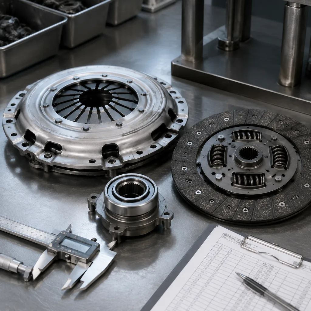
Bench-fit verification with mating timing sprocket, phaser, actuator, followers, lifters, cam sensor target, and retaining components where the interface is application-critical.
Rotation torque or free-turn check in a reference cylinder-head fixture when the buyer can provide fixture data or a validated sample head.
20–30 minute oil-wetted rig or functional rotation check for high-risk launches, focused on abnormal noise, oil-feed alignment, and early contact pattern.
Salt spray or corrosion-resistance checks for packaged storage if the buyer specifies extended warehousing, sea freight, or humid-market distribution.
Packaging drop or vibration testing where long-distance export handling, mixed cartons, or parcel delivery are expected.
Do not borrow approval logic from unrelated parts. For braking products, standards such as SAE J2527 may be relevant, but camshafts are engine components and require validation based on drawings, customer specifications, quality planning, and the intended duty cycle. Engine emissions standards such as ECE R-83 may apply at vehicle system level; they do not by themselves approve or certify a replacement camshaft.
A practical inspection plan is strict at the beginning and lighter only after evidence builds. Many buyers inspect first samples at 100% for critical dimensions, then reduce routine incoming inspection after two or three conforming shipments. High-warranty markets should keep retained samples from the first bulk batch for later claim comparison.
Driventus applies APQP-style planning, incoming material control, in-process inspection, and final inspection under its quality system. Buyers should request the inspection items needed for their own market surveillance, incoming quality control, and warranty review.
What repeatable supply looks like
Importers and multi-location repair chains are not buying a single good sample. They are buying repeatability. That requires batch traceability, stable packaging, documented change control, and clear acceptance criteria, especially when the same programme covers mixed vehicle-parc demand across the EU, UK, North America, Australia, Brazil, and other export markets.
A practical supplier file should include:
IATF 16949:2016 and ISO 9001:2015 certification status.
Control plan and process flow for the camshaft family, covering casting or forging, rough machining, heat treatment, straightening, grinding, drilling, deburring, washing, rust prevention, and final inspection.
Sample inspection report and production part approval evidence agreed with the buyer.
Batch coding method, traceability period, and retained-sample policy, ideally linking carton label, shaft marking, material lot, heat-treatment lot, and inspection lot.
Packaging specification with VCI bag or anti-rust oil, end protection, separator design, carton strength, pallet pattern, and storage guidance.
Labelling format, barcode requirements, country-of-origin statement, gross/net weight, and customer reference rules.
Non-conformance handling, corrective action process, 8D timing, and change-notification rules for material, tooling, heat treatment, process route, subcontractor, or inspection method.
For a camshaft Mercedes-Benz aftermarket replacement, substitution rules matter. A shaft used across several engine codes may still need separate validation if the timing feature, oil feed, follower interface, actuator connection, or bank position differs by application. Catalogue similarity is not enough reason to combine references.
Commercial terms should be agreed before sampling, not after the first pieces are approved. A new or low-volume camshaft may require tooling, fixture, or gauge cost. An existing programme may only need carton artwork and sample inspection. Typical aftermarket MOQ logic is 50–100 pieces for stocked references, 200–500 pieces for private-label packaging, and 500–1,000 pieces or more where new tooling, dedicated fixtures, or special heat-treatment validation is needed. Final MOQ depends on shaft length, material route, machining cycle time, packaging format, and whether the buyer accepts mixed references in one shipment.
Compare price on the same basis: material route, hardening process, included inspection report, packaging, rust-prevention period, Incoterms, currency, tooling amortisation, and spare packaging components. Lead time commonly splits into 7–15 days for drawing/sample review, 20–45 days for sample manufacture when tooling exists, 45–75 days when new tooling or fixtures are needed, and 30–60 days for repeat production after order confirmation, subject to capacity and material availability.
Where an existing aftermarket reference does not match the required geometry, Driventus can review drawings, samples, or performance targets for custom manufacturing. This may suit private-label ranges, regional fleet demand, low-volume service parts, or discontinued applications.
When the return is not a camshaft defect
Many camshaft warranty returns begin as system problems. The shaft is blamed because it is visible during teardown, but the root cause may be oil starvation, debris, timing error, worn mating parts, storage corrosion, or the wrong application selection. Procurement teams should define return-analysis criteria before claims arrive.
Common failure modes include:
Lobe scuffing caused by poor lubrication, incorrect break-in practice, contaminated oil, low oil pressure, blocked spray paths, or incompatible followers.
Journal scoring caused by blocked oil galleries, debris left after engine repair, incorrect bearing clearance, excessive sealant, or inadequate oil supply.
End-face wear caused by incorrect thrust clearance, damaged retaining components, poor cover alignment, excessive axial load, or assembly error.
Corrosion before installation caused by inadequate rust prevention, damaged wrapping, opened packaging, long sea freight exposure, or humid storage conditions.
Abnormal noise caused by incorrect lifter preload, worn followers, oil aeration, insufficient break-in lubrication, or mixed old and new valve-train parts.
Replacement instructions should require inspection of mating parts, oil condition, oil pressure, timing components, lubrication paths, and actuator or sensor interfaces before installation. For repair chains, this improves diagnostic consistency across locations. Make it recordable: oil grade, oil pressure where measured, timing-chain condition, follower replacement status, engine code, mileage, fault codes, and photographs of the failed contact surfaces.
A capable supplier should support claims with sectioning, hardness recheck, surface analysis, dimensional comparison, and review against retained batch samples where appropriate. That evidence is more useful than visual inspection alone, especially when warranty decisions affect several branches or distributors.
Separate early installation failures from longer-service wear. Failures within the first 50–500 km often point to oil starvation, debris, incorrect timing, incompatible mating parts, or severe dimensional mismatch. Failures after normal service mileage require review of wear pattern, hardness, oil contamination, vehicle duty cycle, and whether the same batch shows repeat symptoms.
RFQ checklist: answer these before quoting
A precise RFQ shortens the route from enquiry to usable quotation. It also prevents a common sourcing problem: a supplier samples against the wrong engine variant, the buyer approves the wrong inspection scope, and the issue is discovered only when the first order reaches installers.
Before contacting a supplier, prepare the following:
Vehicle applications, engine codes, model years, body range if relevant, fuel type, emission version if relevant, and target market.
Camshaft position: intake, exhaust, left bank, right bank, or single overhead cam, with quantity per engine and any bank-specific notes.
Existing aftermarket reference, OE-style reference supplied by the buyer, drawing, 2D/3D file, or physical sample if available.
Critical dimensions and tolerances required by the buyer, including lobe lift, journal diameter, overall length, thrust width, oil-hole position, and timing-feature angle.
Target annual volume, first order quantity, forecast pattern, launch timing, and whether mixed references can share one shipment.
Required packaging: neutral, private label, bulk, service kit, customer-specific carton, VCI bag, anti-rust oil, palletisation, and barcode format.
Market destination and documentation needs, including material, origin, REACH-related, and compliance declarations where applicable.
Required inspection report format, measurement items, sample quantity, acceptance criteria, retained-sample request, and pre-shipment inspection rule.
Target price basis, Incoterms, currency, tooling or fixture cost treatment, payment term, target lead time, and phased release requirement.
State the purpose of the first sample order. Is it for dimensional review only, bench-fit testing, vehicle trial, catalogue photography, or customer sell-in? Each route needs different evidence and timing. Prototype acceptance should not be confused with permission for mass production.
If private-label packaging is required, approve artwork, barcode format, carton strength, VCI or anti-rust method, and drop-test expectations before the first production order. Waiting until goods are finished usually creates rework, repacking cost, or launch delay.
Driventus can support standard aftermarket supply or engineered programmes for engine components listed under engine components. For quotation review, application confirmation, and sampling discussion, buyers can request a quote.
Frequently asked questions
Yes. Driventus supplies aftermarket engine components for multiple vehicle applications, including camshaft programmes where fitment data, samples, drawings, or target specifications are provided. Driventus is an independent aftermarket manufacturer; brand names are referenced for fitment only.
Request certification status, dimensional inspection reports, material and hardness records, control plan summary, packaging specification, batch traceability method, and agreed change-control rules. For higher-volume programmes, add sample approval records, retained-sample policy, and pre-shipment inspection criteria.
No. OE-equivalent means the replacement part is designed to match required fit, form, and function for the application. It does not mean approval, endorsement, or authorisation by any vehicle manufacturer.
If you are building a camshaft sourcing programme, Driventus can review fitment data, samples, drawings, packaging requirements, MOQ targets, and lead-time expectations before quotation. Send your RFQ details through /contact.html