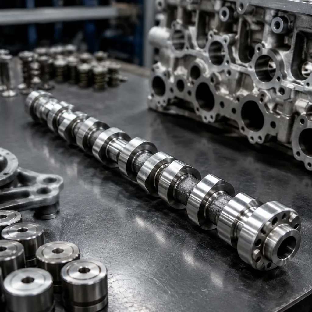
Camshaft for Ford Explorer Replacement: OE-Equivalence Guide
Choosing a camshaft for Ford Explorer replacement is an application decision, not a model-name lookup. Explorer badges cover multiple engines, timing systems, bank positions, trigger patterns, and valvetrain layouts, so the wrong match can still look right on paper. The sourcing risk is practical: noise, misfire, low vacuum, accelerated follower wear, timing deviation, or a no-start after installation. Driventus supplies engine components from Taizhou, Zhejiang, with production controlled under IATF 16949:2016 and ISO 9001:2015. Driventus is an independent aftermarket manufacturer; brand names are referenced for fitment only. This guide focuses on how buyers verify fit, compare replacements, and protect MOQ, price, and lead time without turning the RFQ into guesswork.
Start with the engine code, not the badge
For a reliable camshaft for Ford Explorer replacement, the first filter is engine code. Explorer applications can share a badge while using different camshaft profiles, sensor triggers, timing drives, and phaser interfaces. A quote based only on “Ford Explorer 3.5L” or “Explorer 4.0L” is often too broad to be safe.
At RFQ stage, provide the VIN if available, OE number or cross-reference, displacement, fuel type, bank position, intake or exhaust position, and whether the engine uses VVT/VCT. Left-bank/right-bank and intake/exhaust cams are frequently not interchangeable. The thrust face, dowel, trigger pattern, oil feed, and phaser locating feature can all change.
Useful fitment inputs include:
Buyer input
Why it matters
VIN or engine code
Confirms the actual vehicle build rather than a broad catalogue range
OE reference number
Provides the fastest dimensional and feature match
Bank and position
Avoids intake/exhaust or LH/RH substitution errors
Timing drive type
Confirms sprocket, phaser, keyway, dowel, and thrust layout
Sensor/trigger design
Prevents crank-cam correlation faults and no-start conditions
Follower type
Determines lobe surface finish, hardness, and break-in needs
</tr></thead><tbody> </tbody></table>Ask the supplier to state whether the part is OE-equivalent, catalogue-matched aftermarket, or build-to-sample. If the application spans multiple engine variants, require VIN-based verification before purchase order release so the quote is tied to the actual build, not a generic listing.
What makes a replacement truly equivalent
A camshaft for Ford Explorer replacement only works as an OE-equivalent part if it reproduces the features that control valve timing, follower contact, oil clearance, and trigger synchronization. Horsepower claims matter less than repeatable installation and stable operation.
Request the supplier’s drawing or control plan for the critical dimensions and inspection methods. Exact values vary by OE reference, but these are the control points buyers should expect:
Verification item
What to confirm
Journal diameter
OE-matched bearing size, commonly controlled within ±0.010–0.020 mm depending on journal and drawing requirement
Journal roundness/cylindricity
Micron-level control to maintain oil film and prevent hot spots
Overall length
Matches head casting and thrust-control stack-up; request tolerance and datum faces
End float/thrust interface
Confirm thrust face width, groove, washer, or retainer interface
Lobe lift and base circle
Preserves valve motion and lash geometry; request lift tolerance and base-circle tolerance
Lobe phase/index
Maintains intake/exhaust timing relationship; request angular tolerance in degrees and datum reference
Lobe separation/profile
Confirm against OE master or CAD profile, not only peak lift
Sensor features
Matches reluctor wheel, keyway, dowel, pickup pattern, and phase orientation
Oil passages
Confirm drilling diameter, position, deburring, and cleanliness requirement
Surface finish
Journals and lobes should match follower type; request Ra targets and measurement locations
Straightness/runout
Request total indicated runout limit and inspection support method
</tr></thead><tbody> </tbody></table>Material and process matter too. Common choices include alloy cast iron, chilled cast iron, or steel, depending on the engine family and follower design. For chilled cast parts, ask for hardness and chill-depth data. For steel units, ask for heat-treatment route, case depth if applicable, and temper control. Do not accept “hardened” as a complete specification.
The practical test is simple: if the part installs cleanly, holds oil clearance, keeps timing phase stable, and maintains the intended follower contact pattern, it is doing the job. If the supplier cannot define datum structure, measurement method, and inspection frequency, treat the offer as higher risk.
Verify the part before you buy
Before placing an order, ask for documents that make the camshaft for Ford Explorer replacement easy to compare against the OE reference and the target engine code. The minimum useful package is a drawing or critical-dimension sheet, material and heat-treatment records, and first-article data.
A practical pre-purchase inspection package should include:
Document or record
Buyer action
2D drawing or marked critical-dimension sheet
Check that fitment-critical features are dimensioned and toleranced
Material certificate
Confirm alloy grade or casting specification and batch link
Heat-treatment record
Review hardness range, case/chill depth where applicable, and furnace batch traceability
First-article inspection report
Compare measured values with drawing limits before bulk approval
Surface finish report
Confirm journal and lobe Ra values at defined measurement points
Runout report
Confirm shaft straightness after machining and heat treatment
Cleanliness/deburring check
Confirm oil holes and grooves are free from burrs, chips, and blocked passages
Packaging specification
Confirm rust prevention, separators, end protection, and carton strength
Traceability method
Verify batch code, date code, label format, and link to inspection records
</tr></thead><tbody> </tbody></table>Request material and heat-treatment details because wear resistance depends on both the base material and process control. Surface finish, runout limits, and end-face geometry matter as well; they affect oiling, follower wear, chain or phaser alignment, and timing stability. For incoming inspection, many buyers use AQL sampling on routine shipments and 100% checks on first shipments or new revisions. At minimum, measure journal diameter, overall length, trigger feature orientation, visible casting or machining defects, and packaging condition before stock release.
If the part will be sold under a private label or into a fleet program, confirm packaging, traceability, label content, and revision control before approval. Driventus can support program-specific documentation through custom manufacturing when a buyer needs a controlled drawing, private-label packaging, or a variant matched to a regional fleet application.
Where replacement jobs usually fail
Most sourcing mistakes show up after installation, not at quotation stage. The failure modes are predictable, which makes them useful as a checklist when comparing suppliers.
The most common problems include:
Wrong bank or position: intake and exhaust cams, or left and right units, are treated as interchangeable when they are not.
Trigger mismatch: the reluctor wheel, keyway, or phase orientation does not match the sensor logic.
Thrust mismatch: end float, washer stack-up, or thrust-face geometry is off.
Surface mismatch: lobe finish or hardness does not suit the follower type.
Dimensional drift: journal diameter, runout, or overall length falls outside the target build.
Cleanliness issues: burrs, chips, or blocked oil holes lead to early wear or oil starvation.
If any of those are present, the part may still look correct in a catalogue photo. It may even pass a quick visual check. That is why buyer-side verification should focus on the features that affect timing, oil film, and sensor correlation.
A good supplier will help you separate fitment issues from installation issues. Ask for the measured values, the datum used for each check, and the inspection frequency. When a supplier can explain why a part matches a specific engine code and not just a model year, risk drops fast.
How the validation file should be built
For procurement teams, the most useful validation package for a camshaft for Ford Explorer replacement starts with first-article dimensions, hardness readings, surface finish data, runout results, and a short endurance summary tied to the exact part number or OE reference. That file helps buyers confirm the part matches the intended build and stays consistent from batch to batch.
A practical validation plan usually moves in three stages:
Stage
Typical validation activity
Buyer decision
Sample or reverse-engineering stage
OE sample measurement, material identification, profile scan, datum confirmation
Approve whether the supplier has the correct target
First article
Full dimensional report, hardness, surface finish, runout, visual inspection
Approve tooling, CNC program, and inspection plan
Pilot lot
Batch inspection, packaging trial, installation feedback where available
Approve first commercial shipment
Serial production
In-process checks, final audit, batch traceability, retained samples
Release repeat orders and monitor claims
</tr></thead><tbody> </tbody></table>For higher-volume or warranty-sensitive programs, ask whether the supplier performs profile scanning with a cam measuring machine, magnetic particle or crack inspection where applicable, metallographic checks on heat-treated lots, and torque or assembly checks for any fitted trigger wheel or gear. If the camshaft interacts with a phaser or cam position sensor, trigger angle and datum orientation should be verified with a fixture rather than judged visually.
A complete validation file also makes incoming inspection easier at distribution centers, service hubs, or remanufacturing facilities. It reduces claim risk by showing that the part was checked against defined criteria before shipment, rather than relying on visual inspection alone. When volumes are high or warranty exposure is sensitive, a documented validation trail is usually the simplest way to protect service fill rates, reduce returns, and identify whether a field issue comes from the camshaft, installation practice, oil quality, timing components, or another engine condition.
How Driventus supports sourcing decisions
The sourcing logic is straightforward: lock the application data first, then confirm the replacement part against verified dimensions and inspection records. That sequence keeps quoting aligned with the actual build requirement and avoids later disputes over fitment.
Commercial terms depend on whether the camshaft is an active catalogue item, a low-volume service part, or a custom build-to-sample program. Existing-tooling items usually support lower MOQs and shorter lead times. New variants add engineering review, sample development, fixture confirmation, and pilot production before bulk shipment.
Sourcing scenario
MOQ / price / lead-time logic
Existing catalogue item
Lowest engineering cost; MOQ depends on stock and packaging; fastest quotation and shipment
Existing tooling, no stock
Unit price improves with batch size; lead time covers casting or forging, machining, heat treatment, inspection, and packing
New OE reference or regional variant
Higher initial MOQ or sample charge may apply; lead time includes measurement, drawing, tooling or fixture work, PPAP-style review, and pilot run
Private-label program
Price depends on carton, label, corrosion protection, barcode, and pallet specification
Mixed SKU order
MOQ can sometimes be managed by combining compatible production batches, but inspection and packing remain SKU-specific
</tr></thead><tbody> </tbody></table>Compare quotations on the same basis: part number, engine code, bank or position, material, included documents, packaging, warranty expectation, Incoterms, and inspection level. A lower unit price is not comparable if it excludes rust-preventive packaging, batch traceability, dimensional reports, or private-label packing. For repeat programs, share forecast volume by month or quarter; that supports production planning, raw-material booking, and better lead-time stability than one-off spot orders.
For buyers sourcing a camshaft for Ford Explorer replacement across multiple channels, this approach creates one technical standard for aftermarket resale, service stock, and remanufacturing programs. With the application data fixed early, sourcing teams can compare offers on a like-for-like basis, reduce returns, and protect availability across regional warehouses.
Frequently asked questions
No. Model year is not enough because Explorer engines, timing systems, camshaft layouts, bank positions, and sensor features vary by engine code and market. Confirm the VIN, exact engine, OE reference, intake or exhaust position, and trigger features before ordering.
Ask for dimensional drawings or a critical-dimension report, tolerances, material and heat-treatment details, hardness data, surface finish and runout records, first-article inspection, packaging specification, and batch traceability. For regulated markets, also request relevant REACH information and quality-system certification.
Yes. Driventus supports B2B replacement programs with OE-equivalent matching, program-specific packaging, batch traceability, and documentation. Use the contact page to confirm fitment, MOQ, lead time, packaging, and commercial terms.
If you need a verified camshaft for Ford Explorer replacement, send the engine code, VIN, OE cross-reference, bank/position, forecast quantity, and packaging requirement. We will confirm fitment options, documentation level, MOQ, and lead-time route. Start with a [request a quote](/contact.html).