VVT solenoid dimensions decide more than whether the part slides into the cylinder head. They control seal squeeze, oil-port timing, connector clearance, spool response and how repeatable the valve is after thousands of hot-oil cycles. A coil can test within resistance limits and still create leaks, cam-timing lag, DTCs or harness interference if the locating diameter, O-ring groove, port window or insertion depth is off by 0.05–0.20 mm. For B2B sourcing, treat the dimensional package as a functional specification, not a catalogue attribute. The review should sit beside coil resistance, flow response, leakage, cleanliness, material compatibility and process capability during RFQ, sample approval and receiving inspection. This guide focuses on practical decisions: which dimensions deserve control, where failures usually start, how to compare supplier samples and what to lock before purchase orders scale. Driventus manufactures engine and powertrain components in Taizhou, Zhejiang, under IATF 16949:2016 and ISO 9001:2015 systems, supplying distributors, wholesalers, OEM/Tier-1 programmes and repair-chain buyers in more than 60 countries. Driventus is an independent aftermarket manufacturer; brand names are referenced for fitment only.
Start With the Datum Strategy, Not the Catalogue Photo
A VVT solenoid looks simple from the outside: a body, flange, seal, oil ports and connector. The engine does not see it that way. It sees a fixed relationship between the mounting face, locating diameter, port windows, O-ring grooves, filter screen, valve nose and harness position. If those features are measured from different references by the buyer and supplier, both sides can believe the part is “in spec” while the engine disagrees.
Set the datum scheme before comparing samples. A practical approach uses the mounting face as Datum A, the locating outside diameter as Datum B and the connector centreline or bolt hole as Datum C. That structure keeps port position, insertion depth and connector orientation tied to the same installation logic the cylinder head uses. It also reduces arguments when tooling cavities, machining offsets or connector mould revisions change.
If no approved drawing exists, reverse engineering should begin with at least 3–5 OE or proven service samples. Measure across more than one lot where possible. One used sample with a worn O-ring or bent bracket is not a specification.
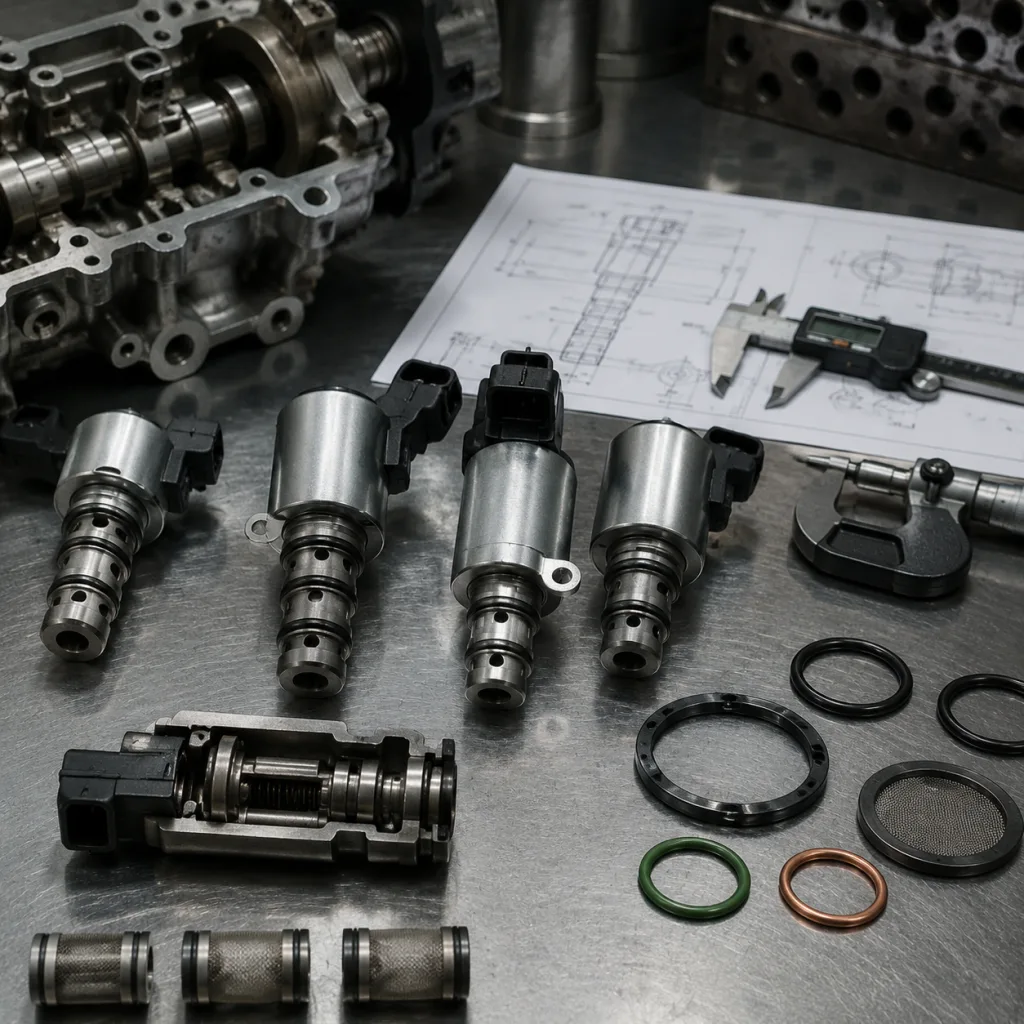
Dimensions worth ballooning include:
Overall length from connector end to valve nose, usually controlled within ±0.20–0.50 mm
Locating body outside diameter, cylindricity and roundness, often within ±0.03–0.08 mm for bore fit
Insertion depth from mounting face to valve nose, usually critical for port alignment
Mounting flange thickness, bolt-hole diameter, counterbore and sleeve details
Oil port width, height, axial position, angular position and edge radius or chamfer condition
O-ring groove diameter, width, depth, side-wall finish and lead-in chamfer
Seal land diameter and surface finish, commonly around Ra 0.8–1.6 µm unless the design requires otherwise
Filter screen diameter, mesh retention, crimp height and clearance to adjacent ports
Spool stroke, plunger travel, return spring free length and internal sleeve position
Do not approve a VVT solenoid from photos, vehicle lists or a single cross-reference. A useful approval pack includes a 2D drawing, ballooned inspection report, master sample, fitment cross-reference, coil-resistance range, flow/leakage data and packaging label sample. Driventus can align drawings, samples and application data through our catalog and engine component sourcing support at /products/engine-components.html.
Dimension Table: What to Control Tightly and What Can Float
Not every number deserves the same tolerance. Over-controlling cosmetic or non-functional dimensions raises cost without improving field performance. Under-controlling the locating diameter, O-ring gland or port position creates failures that are expensive to diagnose. Use the table below as a procurement screening tool, then finalize each value against the approved application drawing and master sample.
Feature
Typical control range
Common tolerance target
Procurement risk if uncontrolled
Locating body OD
18–35 mm
±0.03 to ±0.08 mm; roundness ≤0.03 mm where bore fit is tight
Bore interference, oil leakage or loose fit
Overall length
55–115 mm
±0.20 to ±0.50 mm
Installation interference or insufficient insertion
Insertion depth from flange
25–85 mm
±0.10 to ±0.30 mm
Port misalignment or contact with internal engine features
O-ring groove width
2.0–4.5 mm
±0.05 to ±0.10 mm
Seal extrusion, cutting or compression loss
O-ring groove depth
Application specific
±0.03 to ±0.08 mm; verify seal squeeze against O-ring section
Excessive squeeze, leakage or premature seal wear
Oil port position from datum face
8–45 mm
±0.05 to ±0.15 mm
Reduced oil flow or incorrect cam phaser response
Oil port width/height
1.0–6.0 mm typical
±0.05 to ±0.12 mm; burr height normally controlled below 0.03 mm
Flow restriction, spool sticking or contamination release
Mounting hole diameter
5–8 mm
±0.10 mm typical
Bolt misalignment or assembly stress
Flange thickness
4–10 mm
±0.10 to ±0.20 mm
Clamp load variation and sealing instability
Connector envelope
Application specific
Drawing controlled; check with mating-harness gauge
Harness interference or failed lock engagement
Terminal position
Application specific
Gauge controlled; terminal depth often ±0.20 mm or tighter
Poor contact, intermittent signal or assembly failure
Spool stroke
0.5–2.5 mm
Functional test controlled; correlate with flow curve
Slow actuation or unstable oil metering
</tr></thead><tbody> </tbody></table>The key question is not “what are the standard VVT solenoid dimensions?” There is no universal size. The better question is “which dimensions affect sealing, installation or hydraulic response on this engine family?” Those become critical-to-quality items.
For high-volume programmes, require capability studies on critical characteristics. A common starting point is Cpk ≥1.33 for major dimensions and Cpk ≥1.67 for sealing- or function-critical dimensions once stable production data are available. The usual CTQ list includes locating OD, O-ring groove geometry, oil port position, connector lock features and any dimension that controls engine installation or valve response.
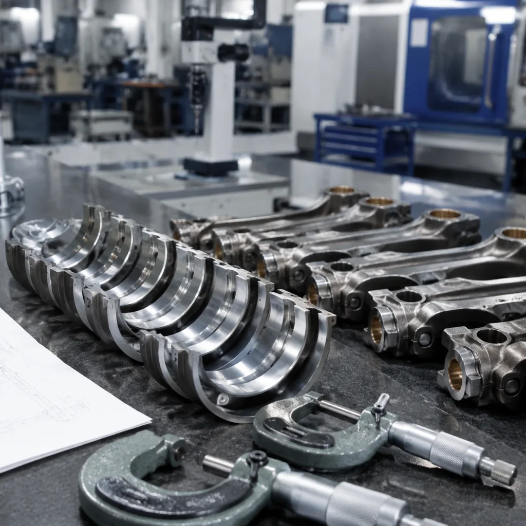
Failure Modes Hidden in Materials, Coatings and Seal Geometry
Many dimensional failures are created after machining. Plating adds thickness. Crimping distorts a screen pocket. A moulded connector shrinks differently between cavities. An O-ring that was correct in free state swells in hot oil and overfills a shallow gland. Material and process choices therefore belong in the dimensional review, not in a separate purchasing note.
A buyer specification should normally define:
Body material: machined steel, stainless steel or aluminium alloy, confirmed by grade or equivalent standard
Spool/sleeve material: wear-resistant steel with controlled hardness, straightness and surface finish
Filter screen: stainless steel mesh with mechanically retained frame and no loose wire ends
Seals: NBR, ACM or FKM selected for engine-oil temperature, additive exposure and market climate
O-ring hardness: commonly 70±5 Shore A unless the approved design requires another grade
Coil housing: glass-filled engineering polymer for heat, vibration and dimensional stability
Terminals: tin-plated or alloy-plated copper-based material with plating thickness agreed by drawing or supplier standard
Seal land finish: often Ra 0.8–1.6 µm, with no axial scoring that can create an oil path
Plating or coating: corrosion protection verified by agreed salt spray duration, appearance criteria and post-plating dimensional checks
Seal areas deserve a system review. Groove width, groove depth, gland fill, side-wall sharpness, seal land finish, coating build-up and lead-in chamfer all interact. Measuring the loose O-ring is not enough. Confirm installed seal squeeze and check whether assembly marks, cuts or rolling occur after insertion into a representative bore.
Watch for these failure triggers: burrs at the groove edge, plating accumulation on the seal land, axial scratches, undersized lead-in chamfers, mixed O-ring compounds and screen crimps that release debris. Each can pass a basic dimensional check and fail during hot-oil testing.
For EU and UK distribution, address compliance early. REACH (EC) No 1907/2006 is relevant for substances in materials and coatings. RoHS may also apply depending on electrical component classification. Driventus manages dimensional, material and process requirements through its quality system, aligned with IATF 16949:2016 and ISO 9001:2015.
Why a Correct Outside Shape Can Still Fail the Flow Test
External fit does not guarantee valve behaviour. A solenoid can seat perfectly in the cylinder head and still respond slowly if internal spool clearance, magnetic circuit geometry, port-edge condition or coil output is inconsistent. For this reason, dimensional reports and functional data should come from the same sample lot whenever possible.
Linked specifications include:
Coil resistance at 20 °C, measured against the application drawing; many 12 V units fall in a broad 6–14 Ω range, but the approved OE-equivalent range controls the order
Insulation resistance and dielectric strength per agreed internal test method, with test voltage and dwell time stated
Current draw at rated voltage and duty cycle, including cold and hot-condition limits if required
Response time under controlled oil temperature and pressure, commonly tested with oil around 80–100 °C for hot-operation correlation
Leakage flow at closed or defined duty-cycle position, recorded against oil viscosity, pressure and temperature
Flow rate versus PWM duty cycle, with the duty-cycle points and frequency stated on the test report
Hysteresis between opening and closing response, especially for applications sensitive to cam-angle stability
Cleanliness level for machined and assembled parts, including particle size limits where specified
Connector retention force and terminal engagement condition, verified with a mating connector or functional gauge
Oil port geometry is the usual weak point. A small burr, edge rollover, chamfer shift or port offset can change the flow curve while the housing still measures within nominal limits. Visual inspection helps, but it should be backed by gauge checks, flow testing and sample teardown during approval.
Freeze the port-edge process after approval. Changing from drilling to punching, laser cutting or a different deburring method can alter hydraulic response without changing the drawing callout. The same logic applies to sleeve pressing, spool finishing and cleaning.
IATF 16949:2016 and ISO 9001:2015 do not define one VVT valve size. They require controlled processes, traceability, corrective action and continuous improvement. Vehicle emissions regulations such as ECE R-83 relate to engine system performance, but they do not replace part-level dimensional validation, hydraulic testing or buyer-approved application sign-off.
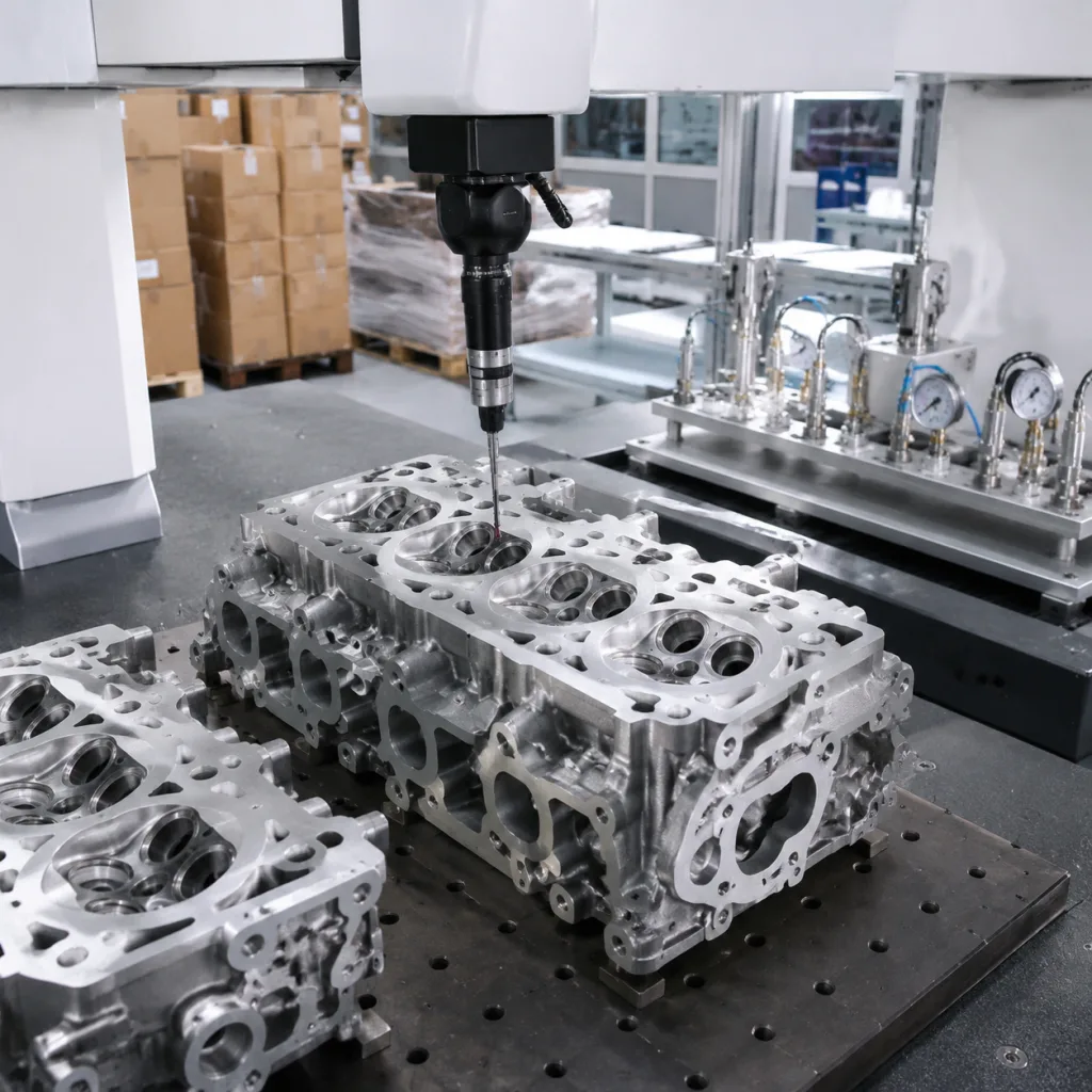
Incoming Inspection: A Practical Step-by-Step Gate
Incoming inspection should sort risk, not generate paperwork for its own sake. Start by separating critical, major and minor characteristics. Critical items affect sealing, oil metering, connector engagement or engine fitment. Major items influence assembly reliability and durability. Minor items cover appearance, handling and packaging unless they can affect function.
Use this gate sequence:
1. Document review: Check drawing revision, application list, OE cross-reference format, material declaration, control plan, process flow, inspection standard and change history. 2. Dimensional inspection: Measure body OD, flange, O-ring grooves, port location, bolt hole, connector envelope and total length using calibrated calipers, micrometers, pin gauges, height gauges or optical measurement. 3. Gauge and fixture checks: Confirm connector keying, terminal depth, bolt-hole alignment and insertion fit where dedicated gauges, mating connectors or cylinder-head simulation fixtures are available. 4. Functional bench test: Verify coil resistance, actuation, flow response and leakage against the approved specification, using the same voltage, oil temperature, pressure and duty-cycle points stated in approval documents. 5. Seal verification: Confirm O-ring material, hardness, dimensions, groove compression and visible damage after assembly; retain samples after hot-oil or fitment testing where possible. 6. Cleanliness review: Inspect for machining chips, screen contamination, burrs, crimp debris and residual oil condition, especially around ports and spool movement areas. 7. Packaging and traceability: Confirm batch number, production date, label accuracy, carton strength, corrosion protection and inner packaging that prevents connector or seal damage during export handling.
Inspection frequency should follow programme maturity. For first articles or new tooling, request a full dimensional layout on 3–5 pieces plus functional testing on a larger pilot sample. For stable repeat orders, receiving checks may use ANSI/ASQ Z1.4 or ISO 2859-1 sampling, with tighter AQL levels for critical dimensions. Do not remove critical VVT solenoid dimensions from the supplier control plan just because several batches passed receiving inspection.
For new programmes, request initial sample inspection reports, process flow diagrams, control plans, gauge plans, capability data and testing summaries. For private-label or application-specific projects, custom manufacturing can include drawing development, sample matching, gauge planning and packaging specifications.
RFQ Scenario: Existing SKU Versus New Private-Label Programme
The commercial specification should match the technical uncertainty. An existing validated SKU needs a different RFQ from a new private-label VVT solenoid built from samples. Mixing those two situations is how buyers get unclear pricing, disputed tooling costs and weak accountability for dimensions.
For an existing application, ask for target coverage, engine codes, market destination, OE cross-reference format, current MOQ, unit price breaks, lead time, packaging options and available validation records. Still verify the drawing revision and CTQ dimensions. Catalogue interchange is not approval.
For a new or private-label programme, separate development cost from piece price. Sample matching, drawing work, connector gauges, test fixtures, private-label artwork and packaging plates may be one-time costs. If they are hidden in the unit price, reorder negotiations become messy.
Confirm these points before volume orders:
Target application coverage, engine codes, production years and market destination
Approved drawing revision, golden sample status and whether buyer or supplier controls the drawing
Critical-to-quality dimensions, inspection method, sampling plan and capability target
Coil resistance range, test voltage, PWM frequency, duty-cycle points and operating temperature
Seal material, hardness, oil-temperature requirement and service-fluid compatibility
Material compliance documentation for destination market, including REACH/RoHS declarations where required
MOQ, unit price breaks, tooling or fixture cost, sample cost, lead time and payment terms
Packaging format, private-label artwork, label language, barcode data and carton drop-test expectation
Warranty data requirements, claim threshold, failure analysis process and response time
Change notification rules for tooling, materials, plating, test equipment, production site or sub-suppliers
Requirements for PPAP, sample approval, annual revalidation or customer-specific documentation
A practical price request uses 100/500/1,000/3,000-piece breaks, sample lead time, mass-production lead time after approval and the MOQ required to hold pricing for 6–12 months. For blanket orders, include forecast release rules and mixed-SKU carton assumptions.
Driventus supports B2B sourcing for distributors, wholesalers, Tier-1 supply chains and multi-location repair networks. Typical discussions cover MOQ, annual demand, forecast release, private-label packaging, dimensional validation, functional testing, audit documentation and launch timing. Driventus is an independent aftermarket manufacturer; brand names are referenced for fitment only. To compare application data and start a technical RFQ, buyers can request a quote.
Frequently asked questions
The locating body diameter, insertion depth, mounting flange, bolt hole, O-ring grooves, oil port position and connector envelope are the main fitment controls. Terminal depth and connector keying should also be checked because harness engagement failures can occur even when the metal valve body is correct. For many applications, locating OD and oil-port position need tighter control than overall length.
Sometimes, but only when the dimensional package, oil port layout, connector type, coil resistance and hydraulic response match the target applications. Buyers should validate by drawing, sample inspection, mating-connector check and functional testing rather than relying only on visual similarity or catalogue interchange.
IATF 16949:2016 and ISO 9001:2015 are relevant for manufacturing quality management. REACH (EC) No 1907/2006 may apply to materials and coatings for EU supply. ANSI/ASQ Z1.4 or ISO 2859-1 can support sampling plans where agreed. Application validation still depends on approved drawings, functional tests, dimensional checks and buyer-specific requirements.
If you need dimensional review, sample matching or private-label supply for VVT solenoids, share your drawing, sample photos, target annual volume, packaging requirements and forecast. Driventus can review the programme and respond with technical sourcing options at /contact.html