Valve Stem Seal How to Replace: Practical Workshop Steps
Valve stem seals control the thin oil film between the valve stem and guide. When the seal lip hardens, the garter spring loses tension, the case loosens, or the lip is cut during installation, engine oil can travel into the intake or exhaust port and then into the combustion chamber. Workshops usually see the problem as blue smoke after idle, smoke on deceleration, plug fouling, carbon on the valve head, and oil consumption with no external leak. This guide covers valve stem seal how to replace procedures from both a repair and procurement perspective: when the repair makes sense, what to measure before ordering parts, how to remove and install seals without damaging the stem or guide, and how to validate the result before the engine returns to service. Driventus is an independent aftermarket manufacturer; brand names are referenced for fitment only. For procurement teams, distributors, and repair networks, the rule is the same for a single repair or repeat supply: confirm dimensions, material, installed height, and application data instead of relying on box art or a visual match.
When replacement is justified
A valve stem seal replacement is justified when the fault pattern points to oil control at the valve guide, rather than piston rings, turbocharger seals, crankcase ventilation, or a head gasket fault. The seal can meter oil at the guide, but it cannot correct excessive guide clearance, bent valves, worn stems, blocked breather systems, or high crankcase pressure.
Typical signs include:
Blue smoke after the engine idles and then accelerates
Blue smoke after long deceleration or engine braking
Oil fouling on one cylinder or a small cylinder group
Rising oil consumption with no external leak at the sump, cover, cooler lines, or turbo oil feed and return
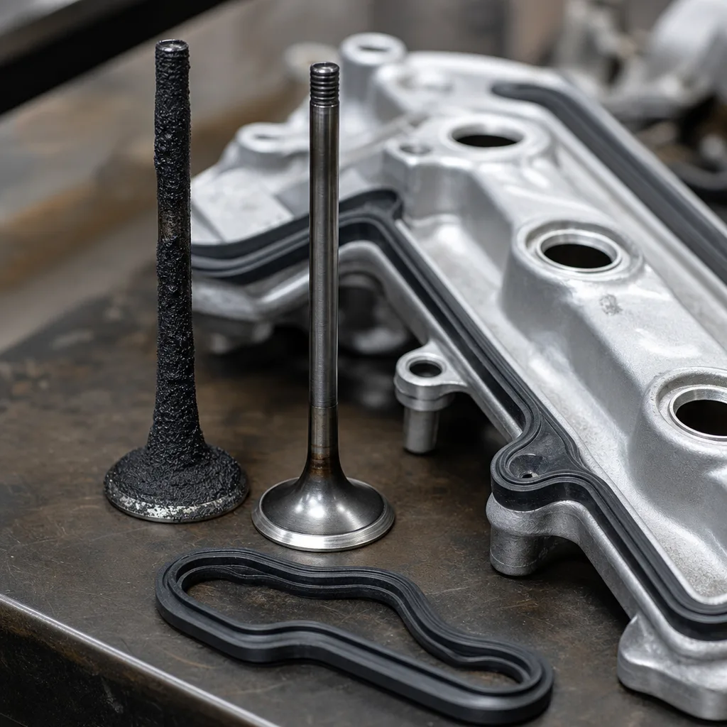
Wet oil deposits in the intake port, exhaust port, or on the back of the valve
Carbon build-up around the valve head that is heavier than on adjacent cylinders
Before disassembly, separate the symptom from the cause. Check the PCV valve, breather hoses, oil separator, turbocharger seals where fitted, spark plugs, intake tract, and exhaust outlet. Compression and leak-down tests help distinguish ring sealing faults from valve-train oil-control faults. They do not identify a bad valve stem seal by themselves, but they reduce the risk of replacing seals when the main issue sits elsewhere.
Guide condition is the key go/no-go point. If valve guide clearance exceeds the engine maker limit, a new seal may reduce smoke briefly, but it will not restore proper oil control. Excess side play lets the stem move against the lip, which can pump oil past the seal or tear the lip soon after installation. Measure stem diameter, guide clearance, and side movement before ordering parts, especially on high-mileage engines, overheated heads, and engines with visible valve-train wear.
Replacement is most reliable when the stem surface is smooth, the guide is within specification, the spring hardware can be reused, and the correct seal design is available for the exact engine code. If the valve rocks in the guide, the guide top is damaged, or carbon ridges are heavy enough to cut the new lip, the cylinder head needs more work before the seal is fitted.
Tools, parts, and measurements
Preparation determines whether the seal fits cleanly or gets damaged before the engine ever runs. Before opening the engine, confirm the replacement seal against the exact engine family, cylinder head layout, and valve position. A seal that looks close can still have the wrong guide interface, lip diameter, installed height, or spring load.
Item
What to verify
Why it matters
Replacement seal
Stem diameter range, guide OD or seat style, seal height, and installed depth
Prevents loose fit, excessive drag, or lip damage
Seal material
FKM, ACM, NBR, PTFE, or other specified compound
Heat, oil chemistry, and ageing resistance must suit the duty cycle
Intake/exhaust identification
Position-specific colour, profile, or part number
Some engines use different seals on hotter exhaust positions
Valve spring compressor
Access around the retainer and spring seat
Prevents bent stems, marked retainers, and lost keepers
Seal pliers or extractor
Straight pulling action on the old seal
Avoids side loading or cracking the guide top
Installer sleeve or mandrel
Correct cone, bore, and shoulder depth
Protects the lip and seats the seal squarely
Measuring tools
Micrometer, small-bore gauge, dial indicator, or service gauge
Confirms stem wear, guide wear, and repair suitability
Support method
Compressed air adapter or clean rope for in-car work
Keeps valves from dropping when the spring is removed
Cleaning supplies
Lint-free cloth, suitable solvent, and non-abrasive carbon removal tools
Removes debris without scratching stems or guides
</tr></thead><tbody> </tbody></table>Measure at the running area of the valve stem, not only at the unworn end. Check guide clearance against the service manual, because acceptable clearance differs by engine, valve position, stem diameter, and operating temperature. Confirm that the seal seats on the guide OD or guide groove as designed, and that the installed height will not interfere with the retainer at full valve lift.
Material selection should follow the engine requirement. FKM is commonly used for higher-temperature oil resistance, ACM may suit certain heat and oil environments, NBR appears in lower-temperature applications, and PTFE designs may be specified where low friction and a different installation method are required. Do not substitute material only by price when the engine has high exhaust temperature, turbocharging, long oil-change intervals, or aggressive oil-additive exposure.
If the engine uses PTFE-type seals, follow the supplier method exactly. Many PTFE seals require a dry lip, a sizing sleeve, and a set period after installation before the engine is rotated or started. Elastomer seals usually need only light compatible lubrication on the stem contact area, not heavy grease packed into the lip. Mixing those procedures is a common cause of early leakage.
Replacement steps
Use a controlled sequence and work one cylinder or one labelled valve group at a time. The aim is simple: protect the stem finish, keep the valve supported, seat the new seal squarely, and return every spring component to its original position unless parts are being replaced.
1. Disconnect the battery, then remove engine covers, coils, plugs, intake hardware, cam cover components, and any access parts required by the service procedure. 2. Clean loose dirt around the cylinder head before opening the valve-train area so debris does not fall into oil returns, ports, or plug wells. 3. Rotate the engine to the correct service position for the cylinder being worked on. If the head remains on the block, support the valves with compressed air through the spark plug hole or with the clean rope method. 4. Confirm valve support before removing spring load. A valve that drops into the cylinder can turn a seal job into cylinder head removal. 5. Compress the valve spring with a suitable compressor. Keep the tool aligned with the retainer so the stem is not pushed sideways. 6. Remove the keepers, retainer, spring, and spring seat in order. Use a tray or marked board so intake and exhaust hardware, and cylinder locations, do not get mixed. 7. Pull the old seal straight upward with seal pliers or the specified extractor. Do not pry against the guide, spring seat, or machined head surface. 8. Inspect the removed seal. A split lip, hardened rubber, loose metal case, broken garter spring, or distorted body can confirm the failure mode and help identify heat or installation issues. 9. Clean the valve stem and guide top. Remove carbon ridges carefully so the new lip is not cut as it passes over the stem. 10. Measure or recheck the stem and guide condition if wear was suspected. If movement is excessive, stop and repair the guide before installing new seals. 11. Fit the protective sleeve over the keeper grooves where required. The grooves are sharp enough to cut many seal lips during installation. 12. Lubricate only as specified for the seal type. Use clean engine oil or the approved assembly lubricant for elastomer designs, and keep PTFE designs dry if the supplier requires dry installation. 13. Press the new seal squarely onto the guide using the correct installer. Apply force through the metal shell or designed shoulder, not through the flexible lip. 14. Seat the seal to the specified depth or positive stop. Do not overdrive it, because a distorted case can lose grip or change lip position. 15. Refit the spring seat, spring, retainer, and keepers. Confirm the keepers are fully locked in the valve groove before releasing the compressor. 16. Tap the retainer lightly with the approved soft tool if the service procedure calls for it, then visually confirm keeper seating again. 17. Repeat the process for each valve, keeping parts separated by cylinder and intake or exhaust position. 18. Reassemble the top end with correct torque values, gasket condition, timing alignment, and connector routing. 19. Start the engine, check oil leaks, listen for abnormal valve-train noise, and inspect smoke after idle, deceleration, and the first heat cycle.
A seal installed off-axis can leak immediately or fail after a short running period. A seal driven too deep can interfere with the guide shoulder or alter the oil-metering position. A seal pressed without a sleeve can be cut by the keeper grooves before the engine starts. If the stem surface is rough, pitted, or worn below specification, polish only within service limits or replace the valve before fitting the new part.
Mistakes that cause repeat leaks
Repeat leaks usually come from diagnosis, fitment, or operating-condition issues, not from the seal material alone. When a replacement fails quickly, review the whole oil-control system before blaming the new part.
Mistake
Result
Corrective action
Wrong application match
Smoke continues or the seal will not seat correctly
Verify engine code, stem diameter, guide OD, and installed height
Worn guide left in service
The seal lip cannot maintain stable contact
Measure guide clearance and repair the head if it is outside limits
Seal driven in crooked
Lip rolls, case distorts, or guide grip is weak
Use the correct installer and apply straight, even pressure
Keeper grooves left uncovered
New lip is cut during installation
Use the supplied sleeve or correct protective cone
Intake and exhaust seals mixed
Uneven oil control or early heat damage
Keep kit positions separated and confirm part markings
Wrong lubrication method
PTFE fails to bed in or elastomer lip runs dry
Follow the seal maker's installation instructions by material type
Carbon not removed from stem
Lip is scratched during fitting or first movement
Clean the stem without damaging the running surface
Excess crankcase pressure
Oil is forced past an otherwise good seal
Check PCV valve, breather hoses, oil separator, and blow-by condition
Retainer-to-seal contact
Seal is crushed during valve lift
Confirm installed height, cam lift, spring hardware, and guide machining
Poor packaging or handling
Lip is flattened before installation
Reject distorted seals and improve transit protection for stock supply
</tr></thead><tbody> </tbody></table>For workshop diagnosis, compare cylinders after the repair. If smoke remains on all cylinders, look closely at PCV restriction, turbocharger oil leakage, ring blow-by, oil level, and oil viscosity. If smoke remains on one cylinder, recheck guide clearance, seal seating depth, stem surface condition, and whether the seal was damaged by the keeper groove.
For fleet, distributor, or export supply, repeat leaks can also reflect catalogue mapping errors. Similar engines may use different stem diameters, guide tops, retainer clearances, or intake and exhaust seal materials across model years. Build application data around engine code, cylinder head variant, valve dimensions, and OE reference where available, then verify against samples before releasing volume stock.
Buying replacements for workshop or export supply
For repeat supply, consistency matters more than the lowest unit price. A valve stem seal is small, but variation in lip diameter, guide grip, spring load, material hardness, or installed height can create visible engine smoke and expensive comeback labour. Procurement teams should treat the part as a precision oil-control component, not a generic rubber item.
Request the following from the supplier:
Dimensional drawing showing valve stem diameter range, guide OD or seat style, seal height, guide interface, and installed depth
Application list tied to engine code, cylinder head variant, intake or exhaust position, and OE reference where applicable
Material declaration for the elastomer or PTFE element, including compound family and intended temperature or oil exposure
Lot or batch traceability that links production date, inspection records, and packaging quantity
Dimensional inspection results for critical features such as lip ID, case OD, height, and concentricity
Packaging that prevents lip flattening, contamination, and deformation during sea freight, air freight, and warehouse storage
Shelf-life and storage guidance, especially for elastomer parts exposed to heat, ozone, or long inventory cycles
Evidence of production control aligned with IATF 16949:2016 and ISO 9001:2015
REACH (EC) No 1907/2006 material compliance where required by the destination market
For B2B buyers, sample approval should go beyond visual inspection. Check the seal against a valve and guide sample, confirm hand-fit and seating behaviour with the intended installer, and compare dimensions across several pieces from the same lot. Where possible, validate on an actual cylinder head so retainer clearance, installed height, and intake/exhaust separation are confirmed before bulk release.
Packaging and labelling deserve attention because many seal failures start before installation. Small seals can be crushed in loose bags, contaminated by dust, or mixed between intake and exhaust positions. For workshop kits, clear compartment packaging and position marking reduce assembly errors. For export cartons, inner packaging should hold shape through vibration, humidity, and stacking pressure.
Often yes, provided each valve can be held closed with compressed air or the clean rope method and there is enough room for the spring compressor and seal installer. If the guide is badly worn, the valve drops, retainer clearance is uncertain, or the head needs machining, cylinder head removal is usually the better route.
No. Some engines use different profiles, materials, colours, or spring loads for intake and exhaust positions because heat load, vacuum exposure, and oil flow are not the same. Keep parts separated by cylinder and valve location during disassembly, inspection, and reassembly.
Confirm valve stem diameter, guide size, seal height, installed depth, material, temperature exposure, intake or exhaust position, and the exact engine application. For export or workshop supply, also ask for lot traceability, protected packaging, shelf-life guidance, and compliance documents tied to the destination market.
If you need valve stem seals matched by stem diameter, guide interface, material, application volume, and packaging requirement, send the engine details and target quantity through [request a quote](/contact.html).