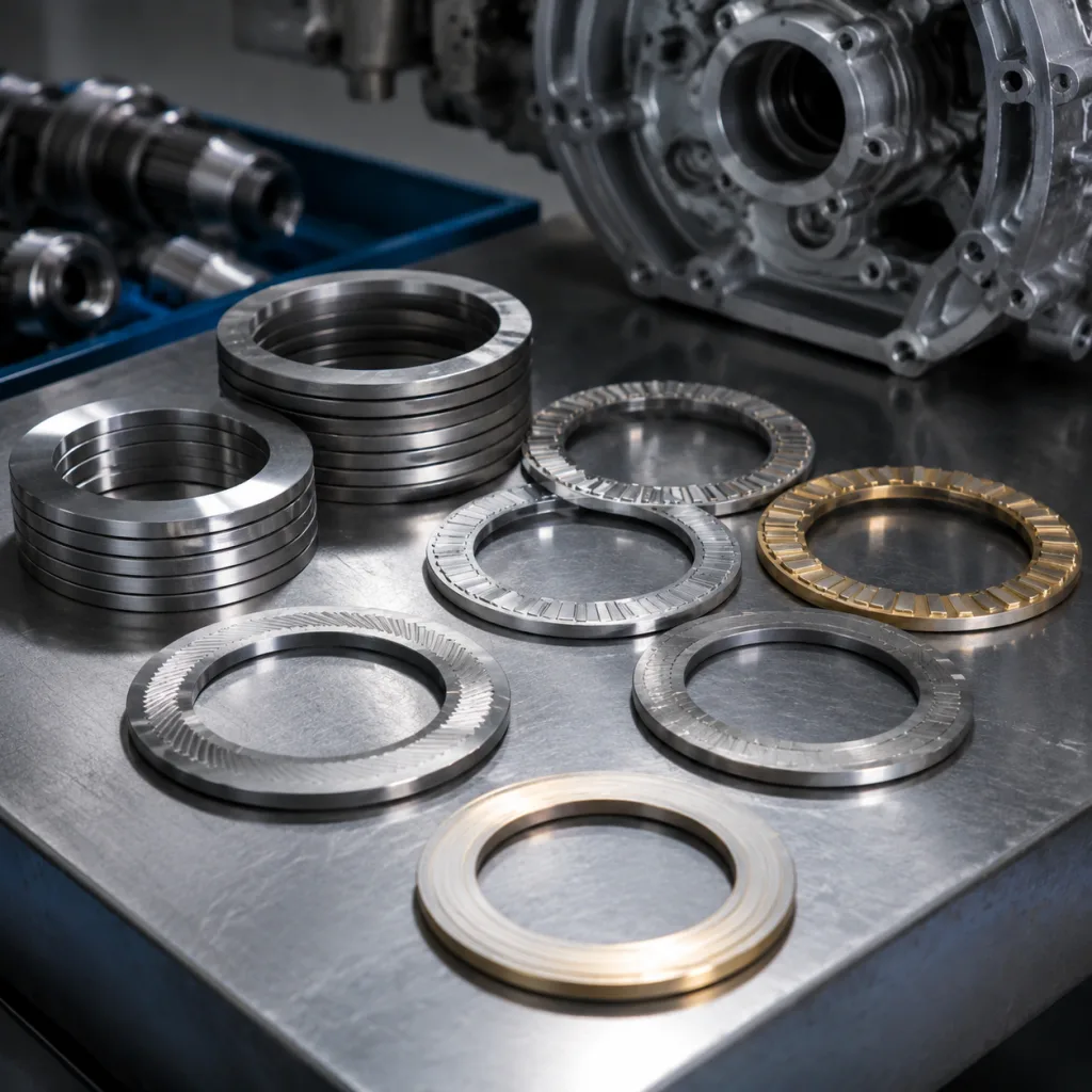
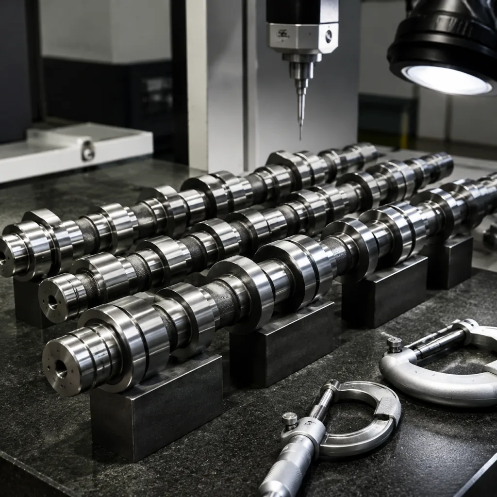
Thrust washers look simple until they set the wrong crankshaft end float. In crankshafts, camshafts, balance shafts and transmission assemblies, the part controls axial movement through a tight stack of housing width, washer thickness, tab location, oil grooves, surface finish and mating-face geometry. For sourcing teams, the question is not “Does this match the engine application?” It is “Will this washer install cleanly, hold oil film, stay located and deliver the specified axial clearance after assembly?” This article breaks down thrust washer dimensions as a buying decision: what to define, where suppliers often fail, how tolerances change cost, and what evidence to request before production release. Driventus manufactures engine and powertrain components in Taizhou, Zhejiang, under IATF 16949:2016 and ISO 9001:2015 production-control systems. Driventus is an independent aftermarket manufacturer; brand names are referenced for fitment only.
Start With the Fit Problem, Not the Part Number
A reliable thrust washer RFQ starts with the functional fit, not only the nominal engine application. Cross-references, samples and legacy drawings are useful starting points, especially for aftermarket programs where references such as OE 06A… are already used in the market. They are not enough for tooling. The supplier still needs measurable thrust washer dimensions tied to the housing, shaft and end-float requirement.
First decide what is being purchased: one half washer, a matched upper/lower pair, or thrust faces included with main bearing sets. That choice affects inspection quantity, packaging count and price comparison. For reverse-engineered parts, measure at least 5 to 10 unworn samples and record the spread. Do not use the average thickness of a used washer as the design nominal unless the mating crankshaft end-float specification confirms it.
Use this decision table before sending the RFQ:
Dimension or feature
Decision it supports
RFQ detail to lock down
Outside diameter
Will the washer seat correctly in the cap or housing?
State nominal OD, tolerance and seating-edge burr limits
Inside diameter
Will it clear the journal, radius or fillet?
Confirm minimum ID against shaft diameter plus chamfer or fillet clearance
Finished thickness
Will end float land inside target?
Specify final thickness after lining/coating; measure at 3 to 6 points per half
Arc length or split angle
Will contact area and wrap match the design?
Define included angle or chord length, not only “half washer”
Tang or locating tab
Will the washer resist rotation?
Give tab width, height, corner radius and distance from datum edge
Oil groove layout
Will oil reach the thrust face correctly?
Define groove width, depth, end radius, angular position and left/right orientation
Chamfer or radius
Will edges avoid shaft fillet contact?
State minimum chamfer or radius and keep the thrust face burr-free
</tr></thead><tbody> </tbody></table>Datums matter. A practical drawing convention is datum A as the thrust face, datum B as the inside diameter, and datum C as the tab or split edge. Groove position and tab position can then be checked from the same references. Without a shared datum scheme, two suppliers may measure the same washer differently and both report “acceptable” results.
For catalogue review, buyers can compare application coverage in our catalog. For low-volume, new or reverse-engineered references, approve the dimensional drawing before production release.
Tolerance Choices That Change Clearance and Cost
Not every dimension deserves the same tolerance. Some dimensions prevent assembly interference. Others control oil film or crankshaft end float. The mistake is to copy a tight tolerance everywhere, raising cost without reducing risk, or to leave finished thickness loose because the washer appears small and inexpensive.
For many passenger-car and light-commercial applications, thrust washer dimensions fall into repeatable sourcing ranges. Heavy-duty diesel, industrial and high-load powertrain assemblies often require larger outside diameters, wider contact areas and thicker bearing layers. Treat the figures below as procurement benchmarks, not universal engineering limits:
Outside diameter: 45 mm to 115 mm for many light-duty engines; large diesel and industrial washers may exceed 150 mm.
Inside diameter: commonly held within ±0.025 mm to ±0.050 mm where shaft clearance is functionally critical.
Finished washer thickness: often 1.50 mm to 3.50 mm, with ±0.005 mm to ±0.015 mm for selective-fit sets.
Selective thickness grades: common increments are +0.05 mm and +0.10 mm; each grade needs its own code, label and inspection limits.
Parallelism: typically 0.005 mm to 0.020 mm depending on washer diameter and bearing-face area.
Flatness: commonly 0.010 mm to 0.030 mm after forming, coating or plating.
Thrust-face roughness: often Ra 0.2 µm to 0.8 µm, depending on lining material and finishing process.
Locating tab width: often controlled to ±0.03 mm to avoid looseness, rotation or installation force.
Groove depth: commonly ±0.02 mm to ±0.05 mm when the groove affects oil feed or contact area.
The buyer check is simple: calculate axial clearance as housing thrust width minus the installed thrust-face stack, then compare it with the engine end-float target. If the target crankshaft end float is 0.07 mm to 0.25 mm, a 0.03 mm drift on each washer face can consume a large share of the working window.
Also define when thickness is measured. Bare metal, post-lining and final coated thickness are not interchangeable. A polymer coating of 0.008 mm to 0.020 mm per face must be included in finished thickness unless the drawing says otherwise. For custom programs, Driventus can support custom manufacturing using samples, CAD data or buyer drawings.
Material Stack-Up: Where the Same Size Behaves Differently
The same washer dimensions can perform differently when the material stack changes. A steel-backed aluminium-tin washer, a bronze-faced washer and a polymer-coated washer may all fit the same housing, but they differ in conformability, seizure resistance, fatigue strength, allowable surface pressure and final thickness control. Material also changes cost. Steel-backed aluminium-tin constructions are usually economical for mainstream aftermarket volume; bronze, overlay and polymer-coated designs require tighter process control and usually higher material cost.
Compare constructions by operating risk, not only unit price:
Construction
Typical use
Procurement watchpoint
Steel backing with aluminium-tin alloy
Passenger-car engines and common aftermarket volume
Confirm lining thickness and final grind or lap process
Steel backing with copper-lead or lead-free bronze
Higher-load diesel and commercial engines
Confirm overlay control and lead-free requirement before quotation
Polymer-coated thrust face
Start-stop, boundary lubrication and low-oil-film conditions
Include coating thickness in final dimensions; request adhesion and wear data
Solid bronze or bimetal washer
Older engines and industrial equipment
Check hardness and wear rate against shaft material; confirm stamping versus machining
</tr></thead><tbody> </tbody></table>Oil groove geometry deserves a separate review. Groove width, depth, end radius, angular position and orientation all affect oil distribution and contact area. Many engine washers use groove widths around 1.0 mm to 3.0 mm and depths around 0.05 mm to 0.30 mm, but the correct value depends on oil supply, shaft speed and thrust load. Too shallow, and lubrication may be starved. Too deep, and the bearing area shrinks.
Chamfers are another failure point hidden in the drawing corner. If the washer meets a crankshaft fillet, a sharp ID edge can wipe oil, mark the shaft or concentrate stress. Define both the chamfer size and the no-sharp-edge condition, such as C0.2 max on non-functional edges and a controlled ID radius facing the crankshaft fillet.
For coated washers, request total finished thickness, coating-thickness range and post-coating flatness. For EU supply chains, material declarations should consider REACH (EC) No 1907/2006. If end customers apply environmental material restrictions, agree the substance reporting requirement before purchase order release.
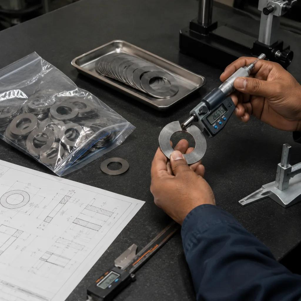
Validation Plan: Prove the Washer Before It Ships
Dimensional validation should be defined before tooling approval. The best control plan links each drawing characteristic to inspection frequency, equipment, acceptance criteria and a reaction plan when results drift. This is especially important for thrust washer dimensions because thin semi-circular parts can flex under gauge pressure and produce misleading readings.
A practical validation package should include:
Initial sample inspection report covering all drawing dimensions, with 3 to 5 pieces per cavity or tooling station where applicable.
Material certificate for backing steel, lining alloy and coating system, including heat number or coil traceability.
Hardness results for backing and bearing layer where specified.
Surface roughness report on functional thrust faces, including Ra value and measurement direction.
Flatness and parallelism readings from calibrated equipment on a defined support fixture.
Cross-section checks for layer thickness on bimetal or coated designs.
Assembly simulation or end-float confirmation using mating reference components.
Capability data for critical dimensions, such as Cpk 1.33 or higher after process stabilization when required.
Measurement method is part of the specification. Finished thickness, flatness and parallelism should be checked with consistent support, clamping force and measuring points. A sensible production plan is 100% visual inspection for burrs, deformation and mixed orientation; first-piece inspection at each setup; and periodic dimensional sampling during the run. For high-risk features such as thickness and tab width, ask for AQL sampling or SPC records rather than relying only on final random inspection.
For tight thickness tolerances, gauge repeatability and reproducibility evidence is worth requesting. When the tolerance is ±0.005 mm to ±0.010 mm, operator technique and part support can look like part variation.
Quality-system certification does not define washer size, but it supports discipline. For production supply, buyers should confirm whether the plant operates under IATF 16949:2016 and ISO 9001:2015. Driventus applies these controls through its quality system, including incoming material inspection, in-process measurement and final sampling.
For North American programs, state the PPAP level in the RFQ. A Level 3 PPAP with dimensional report, material records, process flow, PFMEA and control plan needs more preparation time than a simple sample approval package.
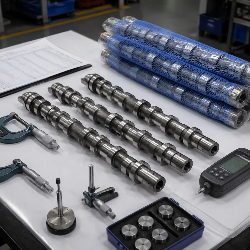
RFQ Walkthrough: From Sample Bag to Quote
A strong RFQ removes the guesswork before the supplier prices tooling, material and inspection. Sending only a vehicle model, a loose reference number or one worn sample usually creates a cheap quote and an expensive sampling loop. The supplier needs the commercial picture and the engineering picture at the same time.
Build the RFQ in this order:
1. State the application, engine code or platform, plus annual volume estimate. 2. Provide drawing or measured sample data for outside diameter, inside diameter, finished thickness, tab and groove geometry. 3. Define material, lining and coating, including lead-free requirements where applicable. 4. Give the target axial clearance or crankshaft end-float range after assembly. 5. Specify surface roughness, hardness, flatness and parallelism targets. 6. Describe packaging, rust prevention and export carton labelling. 7. Confirm inspection report format, PPAP level and any buyer-specific quality manual. 8. Provide incoterm, destination port, forecast and launch date. 9. State target MOQ, annual release pattern and whether the first order is for sampling, market test or regular stock. 10. Share target price level or reference purchase price if available, with currency and incoterm.
When drawings are not available, send 5 to 10 samples and identify whether they are new, used or old stock. Used parts can help with fitment study, but they can also hide wear, deformation or previous production variation. Mating component measurements, especially housing width and crankshaft thrust-face condition, help separate intended design from service history.
MOQ and price depend on strip width, stamping or machining route, tooling ownership, coating batch size and packaging format. For catalogue aftermarket washers already in production, MOQ may be driven mainly by carton quantity and inventory status. For new tooling, the order must usually cover die setup, trial production, inspection time and coating minimum batch charges. Ask for price breaks such as 1,000 sets, 3,000 sets and 10,000 sets, and separate tooling cost from piece price.
Split lead time by phase. A workable schedule may allow 7 to 15 days for drawing review and quotation after complete data is received, 20 to 35 days for tooling and first samples on stamped parts, and 30 to 60 days for bulk production depending on material availability, coating process and documentation. PPAP, special packaging or imported material can extend the timeline.
For aftermarket distributors, also define whether the washer is sold individually, in crankshaft bearing sets or in complete engine overhaul kits. That decision affects packaging, stock codes, MOQ and carton-level traceability.
Failure Modes Buyers Can Prevent Early
Most thrust washer sourcing failures start before production. The drawing is incomplete, the coating is treated as cosmetic, or the buyer compares quotes using OD and thickness only. The part is inexpensive; the failure is not. A small thickness error can change crankshaft axial clearance, concentrate bearing load and create assembly rejection or warranty exposure.
Watch for these preventable failure modes:
Finished thickness is specified before coating, creating excessive assembled thickness.
Tab tolerance is missing, causing rotation, rattle or difficult installation.
Oil groove is copied visually but not measured for depth, radius and position.
Inside diameter is too small for the shaft fillet radius.
Flatness is lost after stamping, heat treatment, lining or coating.
Left-hand and right-hand groove orientations are mixed in packaging.
Standard and oversize thickness grades are substituted without clear labels.
Burrs remain on the thrust face or ID edge where the shaft moves axially.
Price comparison ignores material layer, coating, validation scope and packaging.
Selective thickness grades need special control. If a program includes standard, +0.05 mm and +0.10 mm variants, each grade requires separate marking, inventory location, label and inspection limit. Colour coding, bag labels or laser marking can work if the method does not damage the thrust face or create burrs.
Process details also create failures. Stamping direction can put burrs on the wrong side. Coating can reduce groove depth. Tumbling can round tabs enough to weaken anti-rotation function. Approve a golden sample set after dimensional inspection and keep it as the reference for appearance, groove orientation, edge condition and packaging.
Commercial terms belong in the risk review too. Confirm whether the quote includes tooling amortization, PPAP documentation, export packing, rust-prevention oil, labels and spare sample sets. If annual volume is uncertain, request a revalidation plan for long storage and a price-review trigger for material surcharges instead of accepting an unrealistic first quote.
Driventus is an independent aftermarket manufacturer; brand names are referenced for fitment only. Any OE reference is used to identify application compatibility and support dimensional study, not to claim approval or endorsement by a vehicle manufacturer.
Frequently asked questions
Finished thickness, inside diameter, outside diameter, tab geometry, oil groove layout, flatness and parallelism are the main control points. Finished thickness is the most clearance-sensitive dimension because it directly affects crankshaft end float after assembly. Buyers should define whether thickness is measured after lining or coating and specify the measurement points.
Yes, but sample-only development needs careful measurement and confirmation. Used parts may be worn or distorted, so Driventus normally recommends checking sample data against CAD, buyer drawings or mating component measurements before tooling release. For practical sourcing, send 5 to 10 samples if possible and identify whether they are new, used or old stock.
IATF 16949:2016 and ISO 9001:2015 apply to quality management and production control. REACH (EC) No 1907/2006 may apply to chemical and material compliance for EU supply chains. Dimensional limits still need to come from the buyer drawing, inspection plan and end-float requirement.
If you are comparing thrust washer dimensions for a new sourcing program, send drawings, samples, target annual volume, MOQ expectation and required lead time for engineering review. You can [request a quote](/contact.html).