Low oil pressure, bearing noise, coolant contamination, high oil temperature, and repeat gasket leaks rarely point to one part on their own. In an oil pump failure oil cooler case, the costly mistake is choosing a pump or cooler before proving where pressure, flow, heat transfer, sealing, or contamination broke down. Procurement, warranty, and technical teams need a shared evidence trail before approving volume replacement, supplier claims, or repair-network bulletins.
This article uses a practical sequence rather than a parts-first checklist. It shows how to read symptoms, isolate cooler and pump faults, identify failure modes, set replacement rules, and specify aftermarket oil coolers with enough controls to reduce repeat claims. The focus is B2B: distributors, repair chains, fleet programs, remanufacturers, and private-label buyers who need consistent decisions across many engines.
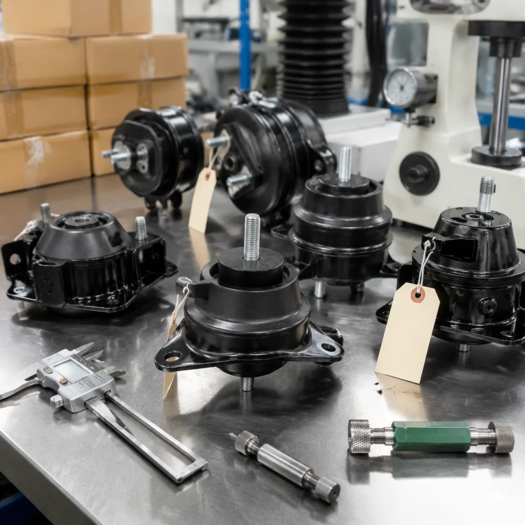
Driventus manufactures engine and powertrain parts in Taizhou, Zhejiang, under IATF 16949:2016 and ISO 9001:2015 controls, supplying B2B customers in the EU, UK, North America, Australia, Brazil, and other export markets.
Symptom Triage: Read the System Before Naming the Part
Start with the data that changes the diagnosis: oil temperature, coolant temperature, oil grade, engine speed, filter reference, and where pressure was measured. A 10–15 °C change in oil temperature can move hot-idle pressure enough to turn a borderline reading into a false failure. Treat the pump, cooler, filter housing, pressure relief valve, oil galleries, bearings, thermostat, coolant circuit, and gasket faces as one system until the evidence separates them.
Symptom observed
Measurable trigger to record
Stronger suspect
First inspection move
Low oil pressure at hot idle
Below service limit at 85–105 °C oil temperature, often under 0.7–1.0 bar depending on engine
Cut open filter, flush galleries, inspect pump, check pickup screen
</tr></thead><tbody> </tbody></table>Two traps cause many repeat claims. First, a low-pressure warning after an oil cooler change does not prove the new cooler is defective. Air in the circuit, a wrong or poorly seated filter, a blocked pickup, worn bearings, or debris holding the relief valve open can create the same complaint. Second, replacing an oil pump while leaving a contaminated cooler in service can feed particles straight back into the repaired lubrication circuit.
For claim triage, pressure values without units and temperature context are weak evidence. A useful minimum file includes cold-start pressure, hot-idle pressure, pressure at 2,000 rpm, oil temperature, coolant temperature, oil grade, filter part number, mileage at installation, mileage at complaint, and photographs of filter media and pickup screen.
A Seven-Step Diagnostic Route That Avoids Parts Swapping
Use the same route for workshop diagnosis, distributor claim review, and returned-part assessment. It keeps subjective descriptions out of the decision and gives buyers comparable evidence across installers and markets.
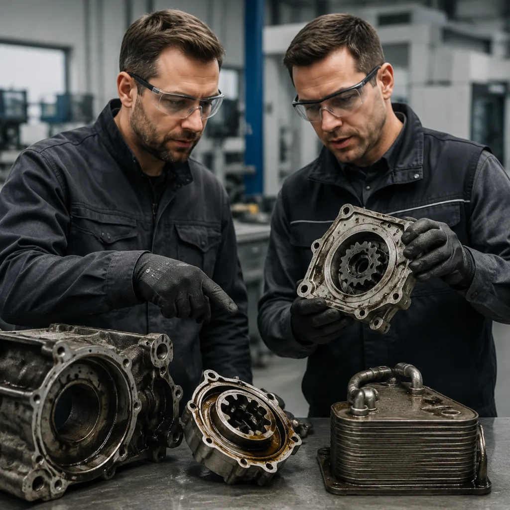
1. Confirm oil grade, condition, and fill level. Wrong viscosity, fuel dilution above about 3–5%, overfilling, or underfilling can change hot-idle pressure and cold-start bypass behaviour. Verify the service specification, sump capacity, and dipstick level before condemning parts. 2. Measure pressure with a calibrated mechanical gauge. Compare cold idle, hot idle, and 2,000–3,000 rpm readings with engine service data. A switch signal or scan-tool value alone is not enough for a warranty decision. 3. Inspect the filter and housing. A collapsed filter, missing centre tube, damaged anti-drainback valve, wrong element, incorrect bypass rating, or mis-seated cap can restrict flow or delay pressure build. Cut the filter open and retain the media when metal or sludge is suspected. 4. Check coolant-oil cross-contamination. Milky oil, oil film in the expansion tank, sludge under the cap, or abnormal sodium, potassium, or glycol in oil analysis supports a leakage investigation. Pressure-test the cooling system at cap rating, commonly 1.0–1.5 bar, and monitor decay. 5. Bench-test the cooler when the design allows it. Use controlled air under water or liquid pressure and monitor bubbles, seepage, or pressure decay. For many passenger-vehicle coolers, a practical bench-screen range is 3–5 bar for the coolant side and 5–8 bar for the oil side unless the drawing specifies otherwise. Do not exceed the agreed production or service limit. 6. Inspect the pump, pickup, and relief valve. Scoring, increased end clearance, sludge, silicone sealant, or metal fragments on the pickup screen point to a supply-side fault that cooler replacement will not fix. Measure pump end clearance, rotor side clearance, and relief-valve movement against the engine manual. 7. Decide whether the cooler is now a debris reservoir. After bearing seizure, camshaft scoring, turbocharger failure, or heavy sludge, a stacked-plate cooler is difficult to prove clean. Replacement is often safer than flushing. If flushing is permitted, define the fluid, direction, particle limit, and verification method before work starts.
A complete warranty file should keep photographs of sealing faces, gasket compression, filter contents, pickup screens, pressure readings, coolant residue, torque tools, and returned packaging labels. Add date code, lot number, installer report, and mileage history. That evidence separates product defects from installation errors, contamination, poor maintenance, and upstream engine damage.
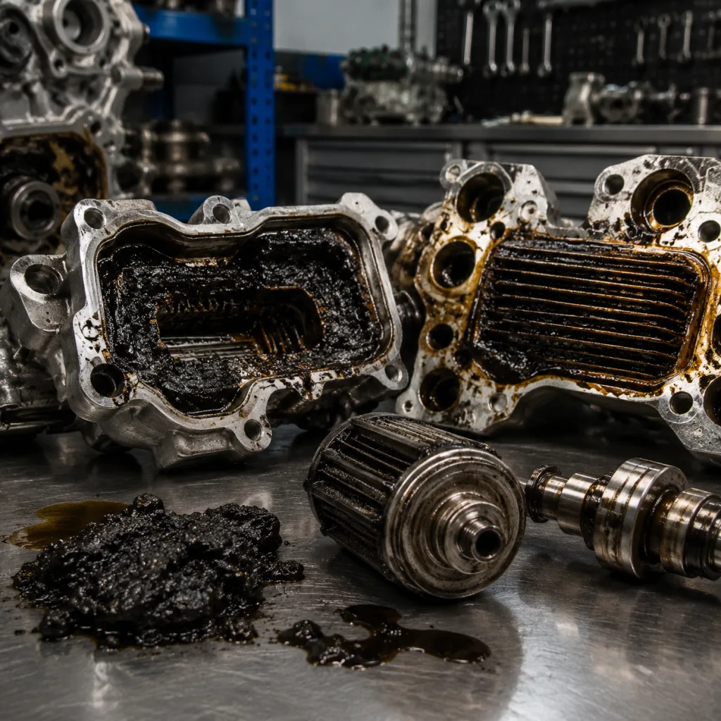
Inside the Cooler: Three Failure Modes That Drive Repeat Claims
Oil coolers usually fail through leakage, restriction, corrosion, thermal fatigue, or movement at the sealing interface. The pattern depends on cooler design, base material, coolant chemistry, engine duty, and installation quality. For sourcing teams, the important question is not only “did it leak?” but “which mechanism would repeat across the lot?”
Oil-coolant leakage
Oil pressure is often higher than coolant pressure while the engine runs, so oil may appear in the cooling system first. After shutdown, residual coolant pressure can push coolant back into the oil side. A cracked core, failed brazed joint, damaged gasket, porous casting, or displaced seal can create this path. Coolant in oil reduces film strength, forms sludge, and can accelerate bearing, camshaft, and turbocharger damage.
Isolate the cooler where possible and test each circuit separately. A production-style pressure decay check may use a defined stabilisation period, 20–60 second hold time, and a maximum decay limit agreed by drawing or control plan. Bubble testing helps locate the leak path. Pressure decay data is better for supplier comparison and warranty trend analysis.
Flow restriction and debris retention
A cooler can hold carbon, gasket material, bearing debris, degraded hose particles, or excess sealant. Stacked-plate designs transfer heat well, but their narrow passages are hard to verify visually. After turbocharger failure, bearing seizure, camshaft scoring, or severe sludge, the cooler should be treated as a contamination reservoir. This is a common reason oil pump failure oil cooler complaints return after only one component is replaced.
Buyer specifications should define internal cleanliness by particle count or gravimetric residue. Many programs set application-specific limits for particles above 200–600 µm and require ports to be capped immediately after final wash. The limit should match engine sensitivity, oil gallery size, and warranty exposure, not a copied value from an unrelated part.
Sealing-face distortion
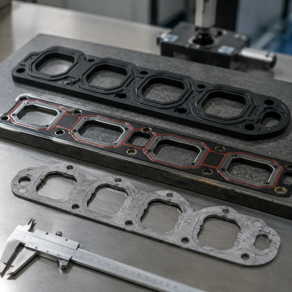
Aluminium housings and cooler bases can distort from overheating, corrosion, impact, or uneven bolt torque. A new gasket cannot compensate for a mating face outside flatness limits or a surface finish that does not suit the seal design. Procurement specifications should include sealing surface finish, flatness tolerance, casting porosity controls, bolt-load assumptions, and gasket compatibility with engine oil, coolant, and expected temperature range.
As an incoming or claim check, use a straightedge or CMM method on the gasket land and record local damage around bolt holes and ports. Typical drawing targets may place sealing-face flatness in the 0.05–0.15 mm range and surface roughness around Ra 1.6–3.2 µm for many elastomer gasket interfaces, but the approved drawing must control the final value.
Buyer Specification Deep-Dive: What Must Be Controlled Before Price
For replacement oil coolers, fitment is only the entry ticket. Warranty performance depends on leak integrity, material stability, internal cleanliness, packaging protection, and traceability. The purchasing file should connect fitment data, sample approval, inspection plan, MOQ, price tier, and lead time so a lower unit price does not quietly remove the controls that protect the program.
Recommended specification points include:
Fitment control: mounting hole position, port geometry, gasket groove dimensions, sensor or pipe interfaces, and hose connection dimensions checked against approved samples, with critical dimensions commonly controlled to ±0.10–0.30 mm depending on feature and process.
Leak testing: 100% pressure decay, immersion, or equivalent leak testing on oil and coolant circuits, with test pressure, hold time, stabilisation time, and acceptance limits recorded by part family.
Material verification: aluminium alloy, stainless steel, elastomer, coating, and brazing material checks according to the drawing, sample approval, or agreed control plan.
Cleanliness control: internal particle limits, washing controls, capped ports, and protective packaging to reduce contamination risk during storage and installation.
Thermal and pressure durability: thermal cycling, pressure pulse, or vibration validation where the application is known for gasket movement, core fatigue, or harsh duty cycles.
Traceability: batch number, inspection record, production date, and packaging identification to support warranty analysis and stock rotation.
Commercial planning should be linked to validation depth. Existing aftermarket references may use carton-based MOQ or small production lots. New tooling, casting changes, or private-label programs usually need higher MOQ to absorb tooling, fixtures, packaging artwork, and PPAP-style documentation. Unit price changes with order band, annual forecast, alloy and gasket cost, test time, packaging level, and whether the buyer requires 100% recorded leak data or sample-based inspection.
Lead time should be split by phase: application confirmation and sample check, tooling or fixture adjustment if needed, pilot run, then serial production. Stocked references can move quickly. New or modified oil cooler assemblies may require several weeks for tooling confirmation, validation testing, packaging approval, and first-article inspection. At RFQ stage, buyers should provide target annual volume, first order quantity, market packaging needs, warranty return rules, and requested inspection reports.
Driventus is an independent aftermarket manufacturer; brand names are referenced for fitment identification only. We can support OE part-number cross-references where supplied by the customer or verified through application data, for example in generic formats such as OE 06A… when applicable. Buyers can review related engine parts in our catalog, including engine component categories at /products/engine-components.html.
Validation Evidence: What Separates a Controlled Program From a Risky One
Oil coolers are not normally certified as stand-alone regulated safety components in the same way as brake or lighting parts. That does not make documentation optional. Importers, distributors, and Tier-1 sourcing teams still need evidence that the manufacturing system controls materials, processes, inspection records, and change management.
Driventus production is managed under a quality system aligned with IATF 16949:2016 and ISO 9001:2015. For EU and UK buyers, material declarations may need to address REACH (EC) No 1907/2006 when substances of very high concern are relevant. Packaging, labelling, country-of-origin marking, and customs documentation should be agreed before serial shipments.
For oil cooler programs, typical validation evidence may include:
Control item
Purpose
Buyer relevance
Incoming material inspection
Confirms alloy, gasket, seal, and purchased component conformity
Reduces batch variation and substitution risk
Brazing or assembly process control
Controls joint integrity, housing quality, and leakage risk
Supports stable leak performance across production lots
Pressure decay leak test
Verifies separation of oil and coolant circuits
Directly linked to contamination and warranty claims
Dimensional inspection
Confirms installation compatibility and gasket compression
Reduces fitment returns and installer rework
Cleanliness inspection
Limits debris entering oil galleries after installation
Helps prevent pump, bearing, and turbocharger damage
Thermal cycling or pressure pulse checks
Assesses durability under repeated hot-cold and pressure loading
Relevant for severe-duty and known high-claim applications
Salt spray or corrosion checks where specified
Assesses surface protection and material resistance
Relevant for harsh climates, coolant exposure, and long storage cycles
</tr></thead><tbody> </tbody></table>A stronger RFQ pack asks for a control plan, process flow, sample inspection report, material declaration, leak-test method, packaging specification, and change-notification rule. For higher-risk applications, request capability data on critical dimensions such as gasket groove width, sealing land flatness, port depth, threaded holes, and mounting-hole position. Where statistical capability is agreed, define the sample size, production run condition, and minimum Cpk target before quoting.
No aftermarket supplier should claim endorsement, approval, or authorisation by a vehicle manufacturer unless formal written approval exists. Fitment references identify application compatibility, not brand affiliation.
Decision Rules: Replace the Pump, the Cooler, or Both?
Base the replacement decision on evidence, not mileage. In many claims, the oil cooler is replaced because it leaks, while the pump remains damaged by previous debris, sludge, or oil starvation. In the opposite pattern, a worn pump is replaced but the contaminated cooler stays in the circuit and releases debris into the repaired engine.
Replace or inspect both components when:
the oil filter contains metallic particles, bearing material, or heavy carbon deposits;
the engine has suffered bearing seizure, camshaft scoring, timing component wear, or turbocharger oil starvation;
oil pressure remains unstable after the cooler, filter, and oil have been changed;
sludge, silicone sealant, gasket fragments, or metal debris is found in the pickup screen;
the cooler cannot be flushed and verified to an agreed cleanliness level;
coolant has entered the oil and the engine has run for an unknown period;
repair history shows repeat low-pressure, high-temperature, or contamination complaints.
For repair networks, a practical rule is to replace the cooler, filter, and oil after any confirmed bearing or turbocharger oil-starvation event unless the cooler design can be reverse-flushed and verified to the buyer's cleanliness standard. Replace or overhaul the pump when pressure remains below service limit after correct oil and filter installation, rotor or cover scoring is visible, relief-valve movement is not smooth, or pickup restriction has starved the pump. If the only confirmed fault is a cooler leak and pressure history is normal, pump replacement may not be necessary, but the oil and filter should still be changed and the cooling system cleaned.
Distributor and repair-chain bulletins should state when a cooler is mandatory with pump replacement and when flushing is acceptable. Clear rules reduce repeat claims, improve installer consistency, and protect replacement parts from contamination-related failures. Driventus can discuss custom manufacturing for oil cooler assemblies, gasket sets, housings, oil pump-related components, and related lubrication parts where customers require private-label packaging, application-specific testing, or drawing-based production.
Frequently asked questions
Yes. A restricted cooler can reduce oil flow, increase bypass operation, raise oil temperature, and retain debris that later damages the pump or bearings. The pump should also be inspected for scoring, pickup restriction, relief valve contamination, and signs of oil starvation before approving a warranty claim.
Usually yes, especially for stacked-plate designs. Bearing debris can remain trapped inside internal passages and re-enter the lubrication circuit after repair. If flushing is considered, the buyer or repair chain should define a measurable cleanliness limit and require evidence that the cooler meets it.
Specify fitment dimensions, leak test method, material requirements, cleanliness limits, gasket compatibility, durability validation, packaging protection, traceability, MOQ, price tier, lead time, and the inspection records required with each shipment. For higher-risk applications, request thermal cycling, pressure pulse, and production inspection data linked to the part family.
If you are reviewing a lubrication-system warranty pattern or sourcing oil coolers for a distribution program, Driventus can provide application review, sampling, and production documentation. To discuss fitment data or request a quote, contact us at /contact.html