Oil Pressure Sensor Symptoms of Failure: B2B Guide
Oil pressure sensor symptoms of failure often start small: a lamp that flickers at idle, a gauge that wanders, or a code that returns after clearing. For B2B buyers, those symptoms matter because they can trigger misdiagnosis, unnecessary returns, and expensive engine claims when the real issue is mechanical oil pressure. That is why the sensor should be treated as part of a wider diagnostic decision, not as a simple plug-and-replace item. This article is written for distributors, repair networks, and sourcing teams that need to separate symptom patterns, sensor fault modes, and specification risks before adding or replacing a part. Driventus is an independent aftermarket manufacturer; brand names are referenced for fitment only.
Start With the Right Decision: Sensor Fault or Oil System Fault?
Oil pressure sensor symptoms of failure are only useful if they are interpreted in context. A warning lamp, unstable gauge, or signal code may point to the sensor itself, but it can also reflect low oil pressure caused by wear, blockage, incorrect oil grade, or a failing pump. The first job is to decide whether the symptom is electrical, mechanical, or mixed.
A practical rule helps. If a calibrated mechanical gauge shows stable pressure while the dashboard lamp, ECU reading, or cluster gauge behaves erratically, the sensor circuit becomes the stronger suspect. If both readings are low, the engine lubrication system needs attention first.
Field symptom
What it often indicates
What to verify first
Lamp on at hot idle only
Switching threshold drift or weak sensor calibration
Hot idle pressure with a mechanical gauge
Gauge jumps or drops suddenly
Intermittent wiring, connector fit issue, or internal sensor instability
Harness movement, pin tension, live data
Code returns after clearing
Signal out of expected range, open circuit, or short to ground
Supply, ground, and output signal checks
Warning appears after oil service
Wrong viscosity, blocked port, sealant contamination, or wrong application
Oil grade, filter, installation method
Oil seepage at sensor body
Seal failure, cracked housing, or over-torque
Housing, thread, washer, and O-ring condition
</tr></thead><tbody> </tbody></table>For workshop screening, the important question is not “is the light on?” but “is the oil pressure reading credible?” That shift reduces unnecessary replacements and helps buyers avoid warranty cases caused by poor diagnosis rather than a true component defect.
How Workshops Should Confirm the Fault, Step by Step
A clean diagnostic sequence prevents sensor replacement from becoming guesswork. The order matters because oil pressure complaints can be electrical, mechanical, or installation-related, and each path needs different evidence.
1. Confirm oil level, oil grade, and filter part number. 2. Warm the engine fully; cold readings can mislead. 3. Listen for mechanical noise from bearings, lifters, chains, phasers, or turbo feed circuits. 4. Read DTCs, freeze-frame data, engine temperature, rpm, and live pressure values where available. 5. Fit a calibrated mechanical gauge at the sensor port if access allows. 6. Compare hot idle and raised-rpm readings with vehicle service data. 7. Check connector locking force, corrosion, oil ingress, and harness strain. 8. Inspect the sensor body, sealing face, and thread condition after removal.
On 3-wire transducers, the basic electrical checks should include reference voltage, ground quality, and signal movement under pressure. For switch-type sensors, the relevant question is whether the circuit opens or closes at the specified threshold. Either way, pressure data should be recorded in bar or psi, not only as pass or fail.
Replacement is justified when oil pressure is within specification but the sensor output is not. If actual pressure is low, replacing the sensor may hide the real defect for a short time and create a false return later. That is why B2B claims should ask for hot-idle pressure, raised-rpm pressure, mileage, DTCs, and batch code before approval.
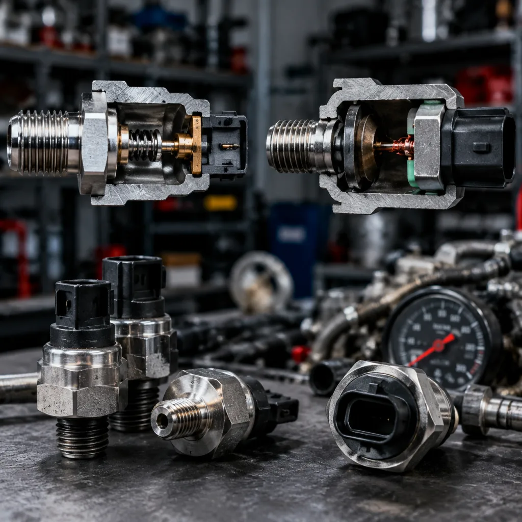
What Fails Inside the Sensor: Switch vs Transducer
The failure pattern depends on design. A pressure switch and a pressure transducer may look similar from the outside, but they fail in different ways and create different complaints in the field.
Pressure switch failure modes
Switching point drift after thermal cycling
Contact bounce under vibration
Diaphragm fatigue from repeated pressure pulses
Oil ingress into the connector cavity
Leakage at the thread or sealing face
Pressure transducer failure modes
Output non-linearity across the range
Offset drift after heat soak
Signal noise caused by weak internal electronics or poor grounding
Terminal fretting, oil wicking, or connector leakage
Wrong calibration curve for the ECU or cluster
The symptom can look the same to the driver. A flickering warning lamp does not tell you whether the problem is a drifting threshold, a noisy output, or a separate oil pressure issue upstream. That is why suppliers should not describe the sensor only as a generic “oil pressure switch” when the application uses a proportional transducer.
Manufacturing controls should match the risk. At minimum, buyers should ask about 100% electrical test, leak testing, thread gauging, terminal retention checks, and traceability by lot or batch. Temperature validation matters as well, because under-bonnet conditions can move from cold start to heat soak very quickly. For sensor families used in high-heat applications, ask whether calibration and sealing remain stable across the expected operating range, not just at room temperature.
Specification Deep-Dive Before Adding a Part Number
Before a new oil pressure sensor is added to a catalogue or private-label range, the specification file should prove more than physical fit. Many parts screw in correctly but still create complaints because the signal curve, switch point, connector keying, or sealing method is wrong.
Key checks for sourcing teams:
Thread size and pitch, such as M10x1, M12x1.5, M14x1.5, or 1/8 NPT
Seal style, including crush washer, O-ring, taper thread, or liquid sealant requirement
Hex size, installed height, and service-tool clearance
Switch threshold or output curve, including tolerance band
Operating, proof, and burst pressure
Oil-side and connector-side temperature limits
Salt spray, thermal cycling, vibration, insulation resistance, and dielectric strength
Packaging protection for threads, seals, and connector locks
Installation torque guidance where the vehicle data provides it
The best sourcing files also include application depth. That means engine code, model year range, fuel type, emission generation, installed position, and OE cross-reference data where it exists. Without that detail, a part can be technically correct and commercially unusable.
For stocked programmes, MOQ should follow demand quality. Fast-moving references can support deeper stock, while long-tail references should begin with sample approval and a pilot lot. If a new connector or calibration is required, expect longer lead times than with catalogue-only items. For generic OE references, treat the number as a fitment guide only, not a statement of manufacturer approval.
Driventus supports engine and powertrain programmes in our catalog, including related engine components where oil-system diagnostics overlap with sealing and pump parts.
A Field Scenario That Explains the Return Risk
Consider a repair chain that replaces an oil pressure sensor after a dash lamp complaint. The vehicle leaves the workshop, the lamp stays off for two days, then the warning returns under idle heat soak. The part comes back as a warranty claim.
If the workshop never measured actual pressure, the supplier cannot tell whether the return came from a bad sensor, a blocked gallery, the wrong oil grade, or a connector problem. If the same claim pattern appears across several vehicles with the same engine code, the issue may be application mapping or installation practice rather than the sensor itself.
This is where buyer controls matter. A strong programme asks for photos of the sensor port, connector, and removed part; a mileage record; DTCs; and hot-idle and raised-rpm pressure readings. If those fields are missing, the claim is not really ready for technical review.
That discipline protects both sides. Repair networks avoid repeat work. Distributors avoid paying for failures that were actually caused by low oil pressure, wrong sealing compound, or a damaged harness. Suppliers, in turn, can isolate lot-level issues much faster when the return data is complete.
What Quality Evidence Buyers Should Ask For
A supplier file should prove that the sensor performs under real operating conditions, not only that it is cheap and available. Because oil pressure sensor symptoms of failure can create expensive labour claims, quality evidence should connect directly to the field complaints buyers actually see.
Buyer request
Evidence to ask for
Why it matters
Fitment confirmation
Dimensional drawings, thread gauges, connector drawings, first article inspection
Prevents install and harness mismatch
Pressure performance
Switch-point records or output-curve data at defined pressures
Reduces false warning lamps and codes
Leak resistance
100% leak test or validated sampling plan with test pressure and hold time
Controls oil seepage claims
Thermal stability
Heat ageing and thermal cycling with post-test verification
Supports hot-engine reliability
Vibration resistance
Vibration validation and terminal retention checks
Addresses intermittent faults
Electrical integrity
Insulation resistance, supply, ground, and signal checks
Prevents open, short, and noise complaints
Traceability
Lot code, production date, carton ID, inspection records
Speeds containment and corrective action
</tr></thead><tbody> </tbody></table>Commercial review should go beyond unit price. A low ex-works cost does not help if the supplier cannot supply batch traceability, technical response, or replacement stock quickly. Buyers should compare MOQ, lead time, packaging requirement, annual volume tier, and warranty support together.
A useful RFQ asks for unit price by quantity break, sample cost, sample lead time, mass-production lead time, payment terms, Incoterms, packaging spec, label format, test report availability, and PPAP or first-article documents if required. If the part needs a new connector or custom calibration, the timeline should reflect that work rather than assuming a catalogue lead time.
Driventus supports documented production control through its quality system. For private-label or variant-specific sourcing, custom manufacturing can be reviewed against drawings, samples, and target annual volume.
No aftermarket sensor should be presented as approved or endorsed by a vehicle manufacturer unless a formal approval exists. Driventus is an independent aftermarket manufacturer; brand names are referenced for fitment only.
Q&A for Reducing Returns and Tightening Support Data
The fastest way to reduce returns is to standardise what gets captured when a claim starts. A short Q&A script helps warehouses, distributors, and repair locations focus on the information that actually separates sensor faults from engine faults.
What should the warranty form capture? Mileage, engine code, oil grade, DTCs, warning behaviour, installation date, batch code, and photos of the connector and thread area.
What should workshop support ask first? Oil level, oil viscosity, filter part number, service interval, and hot-engine pressure readings.
How do you spot a likely sensor issue? Mechanical pressure is stable, but the warning lamp, gauge, or signal output is erratic.
How do you spot a likely engine issue? Both the sensor reading and the mechanical gauge show low pressure.
What should packaging say? Part number, batch code, application family, date or lot code, and fitment notes for sealing and torque.
What if claims cluster by lot or connector style? Isolate stock quickly and review the build record, because that pattern often points to a controlled issue.
A monthly review can track claims per 1,000 units sold, top return part numbers, the percentage of claims with pressure readings, the percentage with DTC evidence, and average response time for technical decisions. Those numbers tell buyers whether to adjust training, packaging notes, application data, or supplier controls.
The best programmes combine correct specification, documented validation, clear lead-time planning, and disciplined return data. That is how distributors keep sensor complaints from turning into repeat labour, avoid misdiagnosis, and choose suppliers on evidence rather than on price alone.
Frequently asked questions
The sensor itself usually does not reduce oil pressure, but a false warning can hide the real issue or delay diagnosis. Workshops should verify actual oil pressure with a mechanical gauge before deciding whether the problem is electrical or mechanical.
Collect mileage, engine code, oil grade, DTCs, warning behaviour, hot-idle and raised-rpm mechanical pressure readings, installation date, batch code, and photos of the connector and thread area. This helps separate product defects from engine wear, incorrect oil, and installation issues.
No. OE cross-references are used for fitment identification only. They do not imply approval, endorsement, or supply relationship with a vehicle manufacturer. Driventus is an independent aftermarket manufacturer; brand names are referenced for fitment only.
For oil pressure sensor sourcing, validation data, MOQ planning, lead-time review, or application range development, contact Driventus to discuss drawings, samples, target annual demand, packaging requirements, and [request a quote](/contact.html).