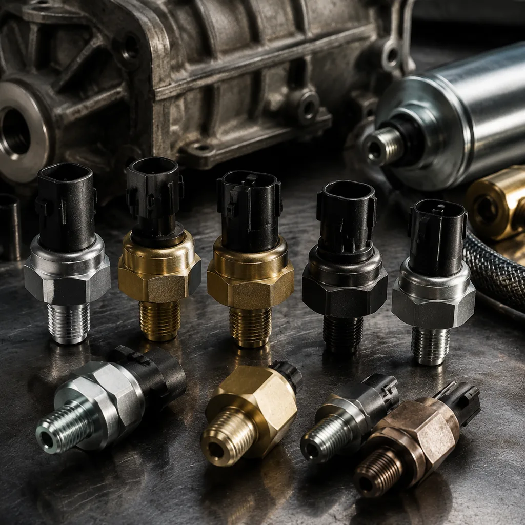
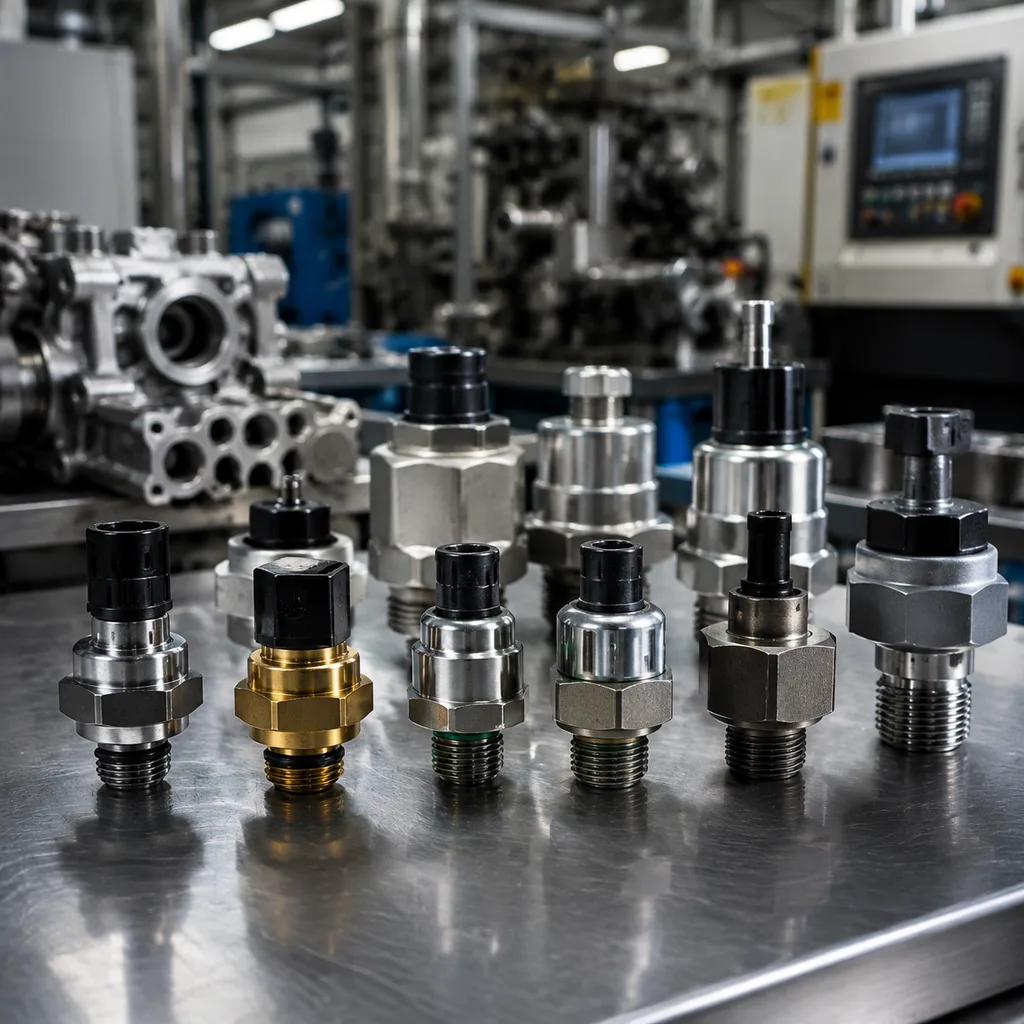
Oil Pressure Sensor Material Grade Comparison for Buyers
For procurement teams, oil pressure sensor material selection is a direct driver of field reliability, warranty exposure, and landed cost. The housing, diaphragm, seal, terminal plating, insulator resin, and potting compound all influence corrosion resistance, response stability, leak risk, electrical continuity, and service life. A useful oil pressure sensor material grade comparison should define the complete material stack, typical pressure range, temperature window, dimensional tolerance, corrosion target, MOQ, price tier, and lead-time impact before sample approval. Most aftermarket engine oil pressure sensors work around 0–5 bar or 0–10 bar gauge ranges, with thread forms such as M10×1, M12×1.5, 1/8-27 NPT, or 1/8-28 BSPT depending on application. The material choice has to match engine oil chemistry, under-hood temperature, vibration, connector exposure, regional road-salt conditions, and the target warranty period. Driventus is an independent aftermarket manufacturer; brand names and OE numbers are referenced for fitment identification only. Our oil pressure sensors are produced under IATF 16949:2016 and ISO 9001:2015 controls, with material traceability, incoming inspection, lot retention, and controlled change approval for critical components. This guide compares common material grades used in oil pressure sensors and explains how buyers can set a practical specification for aftermarket, OEM, or repair-chain supply.
Why material grade changes sensor performance
Oil pressure sensors operate in a hot, oil-wet, vibration-heavy environment, often close to road splash, salt residue, coolant vapour, and connector contamination. Two sensors can share the same thread, connector, pressure range, and external shape yet deliver different service life if the material set and process controls are different.
Key ways material grade affects performance:
- Corrosion resistance: Road salt, oil mist, coolant vapour, and humidity can attack exposed housings, crimps, and plated terminals. A basic zinc-plated steel shell may be acceptable for dry engine bays, while salted-road markets usually need stronger plating control, brass, or stainless options.
- Seal retention: Elastomer chemistry affects compression set, swelling, hardening, and leak risk after heat and oil exposure. Typical targets are Shore A hardness within ±5 points and compression-set verification after heat ageing.
- Thermal stability: Housing, diaphragm, and resin materials expand at different rates, which can influence calibration drift and sealing load. Buyers should define an operating window, commonly -40°C to 125°C for standard designs and up to 150°C for higher-heat programs.
- Electrical reliability: Terminal plating, contact force, and insulator resin affect contact resistance, fretting behaviour, and insulation integrity. Contact resistance should normally be controlled in the milliohm range before and after environmental testing.
- Manufacturing repeatability: Some alloys and resins are easier to machine, form, mould, or crimp consistently, which affects lot-to-lot stability. Thread gauges, crimp-height checks, leak testing, and calibration checks should be defined by lot, not only at initial sample stage.
For purchasing teams, the goal is not to choose the most expensive material by default. The goal is to specify a material set that fits the duty cycle, regional environment, vehicle age profile, and expected warranty period. For broad aftermarket coverage, a supplier should clearly state the base metal, plating system, seal compound, resin family, potting type, pressure range, thread tolerance, and validation method in the technical file. As a working rule, standard aftermarket programs usually balance cost and durability with brass or plated steel housings, stainless diaphragms, HNBR seals, tin-plated terminals, and PA66 or PBT insulation; severe-duty programs justify upgraded corrosion protection, FKM sealing, PPS insulation, and tighter terminal plating control.
Common material grades used in oil pressure sensors
The table below gives a practical oil pressure sensor material grade comparison for the material families most often used in aftermarket and OE-style designs. Exact grade names vary by regional standard, but buyers should insist on a written material declaration rather than generic phrases such as “copper,” “rubber,” or “high-temperature plastic.”
| Component | Common material grades | Typical spec target | MOQ / price / lead-time logic | Main trade-off |
|---|---|---|---|---|
| Sensor housing | Brass such as C36000 / CW614N, stainless steel 304 / 316, plated carbon steel, zinc alloy | Thread tolerance commonly 6g / 6H metric or verified NPT/BSPT gauge fit; plating often 8–12 µm zinc-nickel or zinc with passivation where used | Brass is usually the best low-MOQ option from 500–1,000 pcs per SKU; stainless may add 15–40% unit cost and 1–3 weeks lead time due to machining load | Stainless improves corrosion resistance but raises machining cost; zinc alloy needs careful coating and porosity control |
| Diaphragm | Stainless steel 304 / 316, 17-7PH in some designs, phosphor bronze | Thickness tolerance often within ±0.01–0.03 mm depending on pressure range; pressure proof commonly 1.5× rated pressure or higher by customer requirement | Stainless diaphragm tooling is stable for repeat orders; custom thickness or forming dies may require 30–45 days before PPAP or pilot samples | Higher-grade stainless improves oil and corrosion durability but can be harder to form consistently |
| Seals | NBR, HNBR, FKM | NBR typically -30°C to 100/120°C; HNBR often -40°C to 150°C; FKM often -20°C to 200°C depending compound | NBR is lowest cost; HNBR is the normal upgrade for warranty-sensitive aftermarket; FKM can add 5–20% to sensor cost and may require higher MOQ if compound is not stocked | FKM raises cost; NBR has less heat margin and may age faster in severe duty |
| Insulator | PA66 GF, PBT GF, PPS | PA66/PBT commonly suit 120–140°C class designs; PPS is preferred where continuous heat and dimensional stability are critical | PA66/PBT support faster lead time and lower MOQ; PPS may require resin pre-drying control, dedicated mould settings, and longer sample validation | PPS needs tighter moulding control and generally costs more |
| Terminal plating | Matte tin, tin over nickel barrier, nickel, silver options | Tin thickness often 2–5 µm; nickel barrier commonly 1–2 µm where needed; mating force and contact resistance should be validated with target connector | Tin is standard and price-efficient; nickel barrier or silver is justified for low-current signal stability or harsh connectors but may add cost and extend lead time | Thicker or noble plating increases cost and may require connector compatibility review |
| Potting / encapsulant | Epoxy, silicone-based systems, polyurethane in some assemblies | Epoxy supports moisture sealing and strain relief; silicone improves thermal flexibility; cure ratio, hardness, and void control should be recorded | Standard epoxy is normally shortest lead time; silicone or low-stress compounds may need process trials and extra cure-time capacity | Epoxy can be rigid under thermal cycling; silicone may need stronger process control |