A failed oil pressure sensor can trigger false low-pressure warnings, intermittent dashboard alerts, or inaccurate data to the engine control unit. For distributors, repair chains, fleet maintenance buyers, and private-label programmes, successful replacement depends on more than matching the thread. The part must align with the required pressure range, sealing design, connector geometry, terminal layout, electrical output, and validation level for the application.
This guide explains oil pressure sensor how to replace in a workshop setting, with concrete checks that reduce repeat labour claims, misdiagnosis, and avoidable returns. It also gives procurement teams practical targets for drawings, pressure tolerances, leak testing, MOQ planning, price logic, lead-time control, incoming inspection, production traceability, and warranty feedback. Driventus manufactures engine and powertrain components in Taizhou, Zhejiang, under IATF 16949:2016 and ISO 9001:2015 systems. Driventus is an independent aftermarket manufacturer; brand names are referenced for fitment only.
Start With the Fault, Not the Part
Do not replace the sensor just because the oil warning lamp is on. Low oil level, incorrect oil viscosity, a restricted pickup strainer, wiring damage, poor grounding, or a weak oil pump can produce the same complaint. A structured diagnosis protects the installer, distributor, and end customer from unnecessary repeat repairs.
Use the vehicle service information first, but the following reference values help define a practical diagnostic workflow for many passenger-car and light-commercial applications:
Engine oil level: between the dipstick minimum and maximum marks, checked on level ground after the specified drain-back time.
Oil viscosity: same SAE grade and approval listed for the engine, because high-viscosity cold oil or low-viscosity hot oil can change pressure readings.
Mechanical hot-idle pressure: commonly about 70–150 kPa on many engines, but some applications require higher limits; use the OE value, not a generic pass/fail rule.
Mechanical pressure at 2,000–3,000 rpm: often about 200–450 kPa depending on oil temperature, pump design, and relief-valve setting.
Switch-type sensor threshold: frequently 20–80 kPa for low-pressure warning switches, with tolerance commonly specified at ±10–20 kPa.
Transducer output: commonly 0.5–4.5 V over a defined range such as 0–500 kPa, 0–700 kPa, or 0–1,000 kPa, with accuracy typically requested within ±2–5% full scale.
Connector voltage supply: many transducers use 5 V reference, signal, and ground; many switches use one terminal to ground or a two-terminal circuit.
Recommended checks before removal:
Verify engine oil level, oil grade, service interval, and visible sludge condition.
Inspect the sensor body for oil leakage through the crimp, plastic housing, diaphragm vent, or terminal area.
Check the connector for oil contamination, loose terminals, corrosion, damaged seals, reduced terminal tension, and broken locking tabs.
Inspect nearby harness routing for chafing, heat damage, stretched wires, poor splices, or previous repair joints.
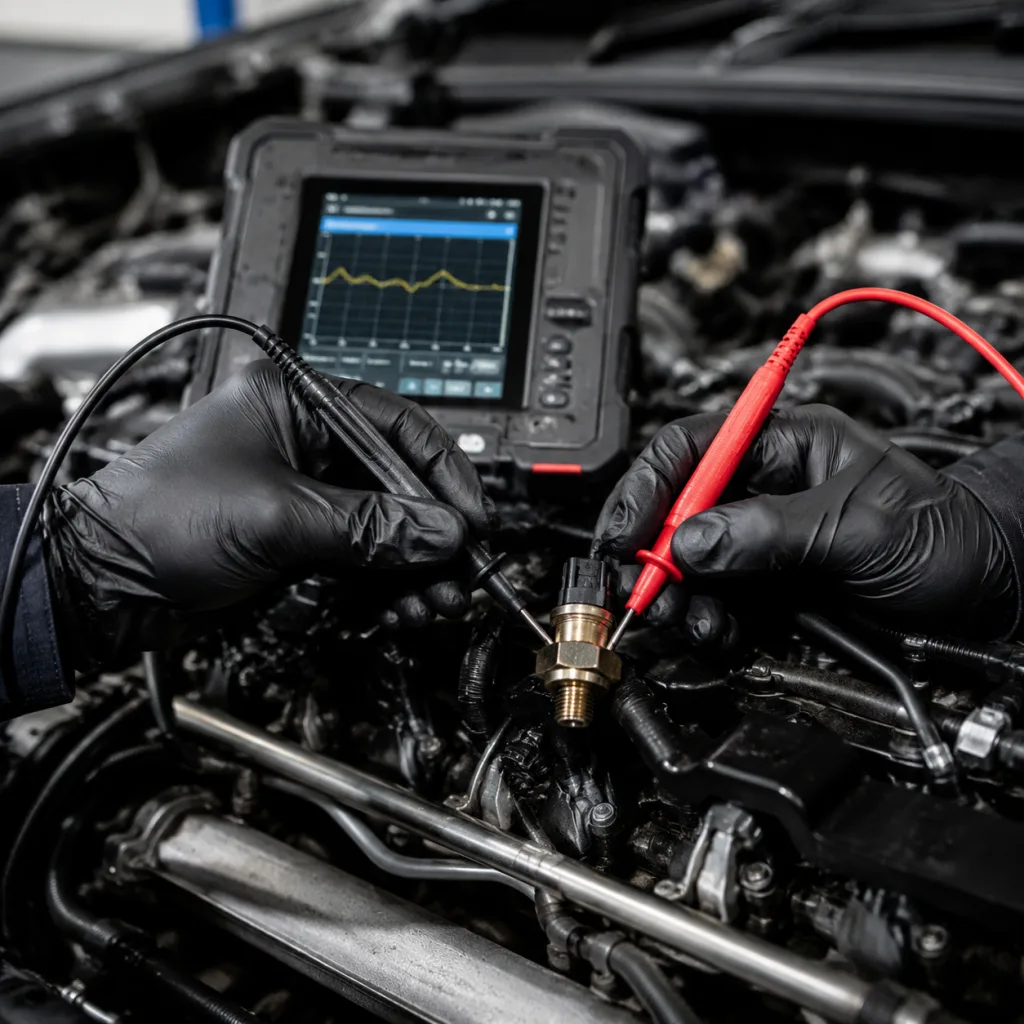
Use a mechanical oil pressure gauge when the warning behaviour does not match scan-tool data or when the service procedure requires direct pressure confirmation.
Compare live data, warning lamp status, or switch state at cold start, hot idle, and raised engine speed.
Confirm whether the part is a switch-type sensor or a variable pressure transducer before ordering.
A switch-type unit changes state at a calibrated pressure threshold. A transducer sends a variable voltage, PWM, SENT, or other signal output across a defined pressure range. Mixing these designs can cause incorrect warning behaviour even when the thread size and connector shape appear similar.
For procurement teams, diagnostic failure modes should feed into warranty coding. Separate categories for leakage, open circuit, short circuit, incorrect calibration, connector mismatch, installation damage, and no-fault-found claims make supplier corrective action more useful. They also help identify whether a claim points to product quality, catalogue data, installer practice, or an unresolved engine oil pressure issue.
Gather Fitment Data Before You Remove Anything
Good preparation reduces cross-threading, connector damage, oil leaks, and wrong-part installation. Select the replacement from verified application data rather than visual matching alone, especially where the same external housing is used with different pressure calibrations.
Item
What to verify
Typical specification detail buyers should request
Thread specification
Diameter, pitch, taper or straight thread
M10×1.0, M12×1.5, M14×1.5, 1/8-27 NPT, 1/8-28 BSPT, or application-specific drawing
Sealing method
Crush washer, O-ring, tapered thread, or specified sealant
Washer ID/OD/thickness, O-ring material and hardness, or sealant location control
Installation torque
OE torque value by thread and housing material
Often 12–25 N·m for small straight-thread sensors; tapered threads require OE-specific control
Electrical interface
Pin count, keyway, latch design, terminal plating
1-pin switch, 2-pin switch, 3-pin transducer, tin or gold flash terminal requirement
Pressure range
Switching threshold or transducer output range
Example: 40±10 kPa switch point or 0.5–4.5 V over 0–700 kPa
Body length
Clearance near filter housings, manifolds, brackets, or starter wiring
Overall length, hex height, connector angle, and heat-shield clearance
Material
Brass, steel, engineered polymer, washer, O-ring, and seal compounds
Oil compatibility, temperature rating, corrosion resistance, and galvanic compatibility
Catalogue data
Engine code, production date range, and OE cross-reference status
Reduces wrong-part claims in multi-market distribution channels
</tr></thead><tbody> </tbody></table>Workshop tools normally include a suitable deep socket or dedicated sensor socket, a torque wrench covering roughly 5–60 N·m, clean lint-free cloth, absorbent material, oil-safe thread sealant if specified, a mechanical oil pressure gauge with the correct adapter set, a multimeter, and a scan tool where applicable. Use the tool profile recommended for the sensor body; adjustable pliers or incorrect sockets can crack plastic housings, round hex surfaces, or load the connector shell.
Do not apply thread sealant to sensors that seal through a washer or O-ring unless the service procedure specifically requires it. Excess sealant can enter oil galleries, contaminate the port, or interfere with grounding on certain switch designs. Where sealant is specified for a tapered-thread sensor, apply only a narrow band on the male thread and keep the first one to two threads free of sealant.
For receiving inspection, buyers should not only count cartons. A practical incoming AQL plan often checks 0.65–1.0 for critical defects such as wrong thread, wrong connector, damaged sealing face, or oil-contaminated terminals, and 1.5–2.5 for major cosmetic or label defects depending on the buyer’s risk level. At minimum, verify thread go/no-go fit, connector engagement, label part number, lot code, sealing washer or O-ring presence, and packaging protection before stock is released.
Buyers can review available engine electrical and lubrication-related parts in our catalog, including related engine components at /products/engine-components.html. For drawings, connector details, and application review, Driventus also supports custom manufacturing for qualified B2B programmes.
Replace the Sensor in a Controlled Sequence
The following procedure is general. Always follow the vehicle or engine service information for access method, torque value, sealing requirements, and any reset or relearn steps.
1. Park the vehicle safely, apply the parking brake, and allow the engine to cool to a safe handling temperature. Hot oil and nearby exhaust components can cause injury. 2. Confirm the repair order records the complaint, oil grade, mileage, and any stored DTCs before parts are removed. 3. Disconnect the negative battery terminal if the service procedure requires it, especially where the sensor is close to the starter motor, alternator wiring, or main power cables. 4. Locate the oil pressure sensor. Common positions include the oil filter housing, cylinder block oil gallery, cylinder head oil gallery, or rear of the engine near the bulkhead. 5. Clean at least 30–50 mm around the sensor and port before removal. Dirt around the port can enter the oil gallery when the sensor is removed. 6. Release the electrical connector by pressing the lock tab. Do not pull on the harness wires or lever against the connector body with excessive force. 7. Inspect the connector terminals. Oil inside the connector may indicate leakage through the sensor body rather than an external gasket leak. 8. Place absorbent material below the sensor location. A small amount of oil may drain from the port even when the sump has not been drained. 9. Remove the sensor using the correct socket. Keep the tool aligned with the sensor axis to avoid cracking the housing or damaging the threaded port. 10. Inspect the removed sensor and the engine port. Look for damaged threads, old washer material, hardened sealant, cracks, or contamination around the sealing face. 11. Compare the removed part with the replacement. Confirm thread, sealing surface, connector keying, body length, pin layout, pressure specification, and batch label. 12. Install the new sealing washer or O-ring if supplied. Reusing compressed or heat-aged sealing parts increases leak risk. 13. If sealant is specified for a tapered-thread unit, apply only the approved oil-resistant sealant in the controlled area and leave the first one to two threads clean. 14. Thread the new sensor by hand for the first three to five turns where access allows. If resistance occurs immediately, stop and inspect the threads rather than forcing the part. 15. Tighten to the specified torque using a calibrated torque wrench. For many small straight-thread sensors the working range is commonly 12–25 N·m, but the service value overrides any generic range. 16. Avoid over-tightening. Excess torque can crack aluminium housings, deform the sensor body, damage tapered ports, crush sealing washers beyond their design range, or shift the pressure element. 17. Reconnect the electrical connector until the lock engages. Confirm that the harness is routed away from heat, moving parts, sharp edges, and oil-soaked insulation. 18. Start the engine and check for oil leakage at idle for at least 60 seconds. Then confirm warning lamp behaviour, switch state, or scan tool pressure data as applicable. 19. Raise engine speed only after confirming oil pressure is present. Compare hot-idle and raised-rpm readings against the vehicle service data if a mechanical gauge is fitted. 20. Road test or run the engine to operating temperature if required, then recheck for seepage after shutdown and after a short heat-soak period. 21. Recheck engine oil level and top up if necessary, following the service specification for oil grade and quantity. 22. Clear related DTCs only after confirming that the pressure signal, warning lamp, and connector are functioning correctly.
This is the core answer to oil pressure sensor how to replace: confirm the fault first, protect the oil port from contamination, match the electrical and mechanical specification, install with the correct sealing method and torque, then verify oil tightness and pressure signal behaviour after fitting.
Verify the Repair and Capture the Failure Mode
A replaced sensor should not be treated as complete until the workshop verifies both oil tightness and signal behaviour. For repair chains and fleet maintenance operators, this step matters because many repeat complaints are caused by unresolved lubrication problems, damaged wiring, or catalogue errors rather than a defective new sensor.
Recommended post-installation record:
Vehicle or engine application, VIN where permitted, engine code, mileage, and production date range.
Customer complaint and diagnostic result before replacement.
Old part failure mode: leak, warning lamp, no signal, intermittent signal, physical damage, connector contamination, or no fault found.
Oil level, oil grade, and approximate oil temperature at time of pressure confirmation.
Mechanical oil pressure result, if measured, including idle rpm and raised rpm values.
New sensor part number, batch code, production date code, and packaging label reference.
Installation torque or service procedure reference.
Connector condition after fitting, including terminal corrosion, oil intrusion, and latch retention.
Leak check result after idle, warm-up, shutdown, and heat soak.
Final scan-tool data, switch state, DTC status, and warning lamp status.
For distributors, packaging labels should support batch traceability from inbound inspection through customer shipment. A practical label should include buyer part number, supplier part number, lot or batch code, quantity, country of origin, production date, barcode or QR code, and carton number. This lets the supplier and buyer compare complaint rates by production batch, application, customer channel, and installation environment.
Warranty review should define measurable acceptance rules before supply starts. For example, external oil leakage at the crimp, terminal area, or threaded joint after correct installation should be separated from cracked housings caused by tool damage. Electrical returns should be checked for switch threshold, output curve, insulation resistance, connector retention, and terminal condition before being coded as supplier defects. A common B2B target is to review any repeated issue above an agreed claim-rate trigger, such as 0.3–0.5% by shipped quantity, although the final threshold depends on product family, application risk, and warranty period.
Driventus uses process controls aligned with IATF 16949:2016 and ISO 9001:2015, including documented inspection, nonconforming product control, corrective action procedures, and production traceability. Our quality system can be reviewed by B2B buyers during supplier qualification.
Relevant compliance checks may include material declarations under REACH (EC) No 1907/2006 for EU importers. Electrical components should also be assessed against customer-specific requirements for connector retention, thermal cycling, vibration resistance, oil compatibility, insulation performance, terminal corrosion resistance, and packaging durability. Do not assume that a visually similar sensor has equivalent performance or the same validation history.
Specify the Part Like a Buyer, Not a Guessing Workshop
When specifying oil pressure sensors for aftermarket programmes, procurement teams should request data that supports repeatable fitment, stable performance, and clear warranty review. Price comparison without engineering detail increases return risk, especially where one housing style covers multiple pressure thresholds, connector variants, or sealing designs.
Suggested sourcing checklist:
Application list with engine code, vehicle platform, production date range, market coverage, and annual demand forecast.
OE part-number cross-references only where verified, using formats such as OE 06A… or OE 11251… when supplied in the buyer dataset.
Thread and sealing drawing with critical dimensions, tolerance notes, washer or O-ring specification, and port engagement length.
Pressure threshold or output curve, including tolerance, test medium, test temperature, and hysteresis where relevant.
Connector drawing with pin layout, keying, terminal material, plating, insertion force, and retention requirements.
Operating temperature range, commonly requested around -40°C to +125°C for engine-bay parts, with higher local heat requirements where specified.
Housing material, seal material, washer specification, salt-spray or corrosion protection detail, and oil compatibility requirement.
Leak test method, test pressure, duration, and acceptance criteria, such as no visible leakage or pressure decay beyond the agreed limit.
Electrical test plan for open circuit, short circuit, insulation, signal accuracy, switch point, and terminal continuity.
Validation expectations for vibration, thermal cycling, pressure cycling, connector retention, and thermal shock.
Production batch traceability, inspection records, process flow, control-plan summary, and sample retention rule.
Packaging specification for bulk, neutral, or buyer-labelled supply, including label data, barcode requirements, bagging, separators, carton strength, and pallet limits.
For commercial planning, buyers should define MOQ, target price, tooling responsibility, and lead-time expectations at RFQ stage. A practical MOQ for standard catalogue sensors is often one export carton to several hundred pieces per part number, while private-label packaging, low-volume variants, or custom connectors may require higher MOQs such as 500–2,000 pieces per SKU depending on component availability and label setup. Sample lead time is commonly 2–4 weeks for existing designs and 6–10 weeks where connector sourcing, tooling, or validation changes are needed. Mass-production lead time is commonly 30–60 days after order confirmation and packaging approval, with longer timing during peak demand or material shortages.
Price should be evaluated as a landed-cost model, not only unit EXW price. The same sensor programme may vary by pressure element grade, terminal plating, sealing washer material, 100% calibration test requirement, packaging format, order quantity, Incoterms, destination duty, and claim-handling terms. Buyers should request price breaks by annual volume or order lot, for example 500, 1,000, 3,000, and 5,000 pieces, and should separate one-time tooling, sample charges, label artwork, and validation costs from the production unit price.
Driventus can manufacture to existing aftermarket specifications or develop buyer-specific variants where tooling, connector sourcing, sample approval, and validation scope are agreed in advance. Typical B2B discussions include forecast volume, MOQ, lead time, PPAP or sample documentation needs, packaging format, Incoterms, destination compliance documents, and warranty handling process.
No aftermarket supplier should claim vehicle manufacturer approval unless a formal approval exists. Driventus is an independent aftermarket manufacturer; brand names are referenced for fitment only.
Frequently asked questions
Often yes, because the sensor is usually above the sump oil level. Some oil may still escape from the gallery. The workshop should confirm the engine layout, allow cooling time, clean a 30–50 mm area around the port, protect surrounding components, and check oil level after installation.
Common causes include reused sealing washers, incorrect sealant, cross-threading, over-tightening, damaged housing threads, old sealing material left on the port, or the wrong sealing design. For many small straight-thread sensors, torque is commonly in the 12–25 N·m range, but the OE service value always takes priority.
Request pressure calibration data, leak test records, connector drawings, material details, batch traceability, and quality-system evidence. For EU supply, material compliance under REACH (EC) No 1907/2006 may also be required. Buyers should also define MOQ, sample timing, mass-production lead time, packaging rules, and warranty coding before placing volume orders.
If you source oil pressure sensors for distribution, repair networks, fleets, or private-label programmes, share your application list, annual forecast, target MOQ, packaging requirement, and technical specification with Driventus. You can [request a quote](/contact.html).