An oil pan gasket job looks routine until the same vehicle returns with a wet flange. The usual causes are not mysterious: a pan lip lifted 0.15 mm around bolt holes, a greasy sealing land, the wrong gasket for a production-date split, or a technician laying a full RTV bead where the service data called for two small corner dabs.
This article treats oil pan gasket how to replace as both a repair process and a parts-program decision. Technicians need a repeatable method. Fleet workshops need fewer comebacks. Buyers need gaskets that survive storage, installation, heat cycling, and warranty review across many bays.
Driventus manufactures oil pan gaskets and other engine sealing components in Taizhou, Zhejiang, with production controlled under IATF 16949:2016 and ISO 9001:2015. Driventus is an independent aftermarket manufacturer; brand names and OE-style references are used for fitment identification only.
Decision first: is the oil pan gasket really the leak?
Do not start by removing the pan. Start by proving the source.
Oil moves. It runs along castings, follows wiring covers, collects on subframes, and is pushed rearward by airflow. The lowest or wettest point under the vehicle is often only the final collection point. A clean, controlled diagnosis prevents a good gasket from being blamed for a filter housing, pressure sensor, drain plug washer, timing cover joint, rear main seal area, or porous casting.
Use this decision path before authorizing the repair:
1. Clean the lower engine thoroughly. Degrease the oil pan flange, timing cover joint, rear seal area, drain plug, oil filter housing, oil cooler, and pressure sensor. Dry with low-pressure air, generally below about 2 bar, so oil and cleaner are not forced into connectors. 2. Run the engine through more than idle. Inspect after idle, road-load, and cool-down. Some leaks only appear when oil reaches roughly 80–95°C or when braking and airflow move oil across the pan. 3. Use dye when the source is uncertain. Add UV dye at the dye maker’s specified ratio, run the engine for 10–20 minutes plus a short safe road-load cycle, then inspect with the correct lamp. 4. Check crankcase ventilation. A blocked PCV valve, collapsed hose, or restricted separator can create positive crankcase pressure and push oil past a new gasket. 5. Inspect the hard parts. Look for cracked pans, stripped threads, pulled bolt holes, distorted flanges, corrosion tracks, and impact damage. 6. Confirm the application. Match engine code, production date, pan material, sump depth, sensor openings, bolt pattern, and any customer catalog cross-reference such as OE 06A… or OE 11251… used in the buyer’s fitment data.
For distributors and repair chains, leak coding should be strict. Separate oil pan gasket leakage from drain plug washer leakage, RTV joint failure, oil cooler leakage, filter housing leakage, rear main seal leakage, and casting porosity. Require claim photos before and after cleaning, installation mileage, failure mileage, oil grade, part lot number, and packaging label. Cleaner evidence shortens supplier disputes and points corrective action at the real failure mode.
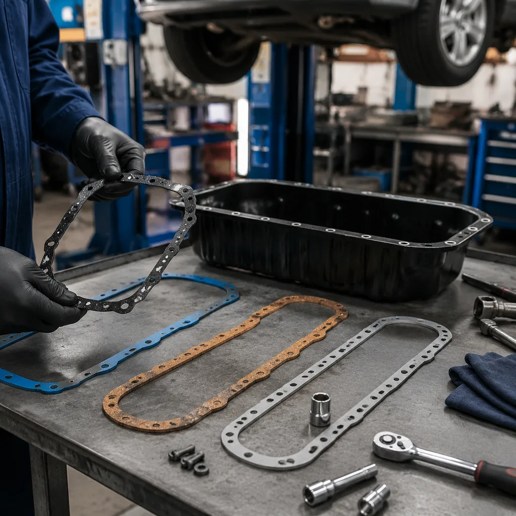
Pre-job gate: parts, tools, and measurements that decide success
Before the first bolt is loosened, confirm the gasket system you are working with. Some pans use a molded rubber gasket. Others use a coated carrier gasket, cork-rubber, composite material, or application-specific liquid sealant at selected joints. Treating all of them the same is a fast route to seepage.
Use the table as a pre-job gate, not a paperwork exercise:
Specify ACM, FKM, NBR, silicone, cork-rubber, or metal/rubber construction; typical hardness windows may be 60–80 Shore A depending on design
Bolt condition
Wrong or stretched bolts create uneven clamp load
Confirm M6/M8 size, length, washer face, coating, reuse rule, and whether any bolts are torque-to-yield
Pan flange flatness
A distorted flange can leak even with a new gasket
Check with straightedge and feeler gauges; a workshop reject point such as >0.15 mm local lift is reasonable unless OE data states otherwise
Sealant requirement
Too much RTV can cause leaks and restrict the oil pickup screen
Instructions should state dry install or define RTV points; common corner dabs are about 2–3 mm high, not a continuous 6 mm bead
Traceability
Enables warranty containment and batch investigation
Lot code, date code, material batch, cavity number where useful, and application label should be visible and scannable
</tr></thead><tbody> </tbody></table>A professional bay should have a calibrated torque wrench covering the expected range, often 5–25 N·m for small pan bolts; plastic scraper; residue-free cleaner; straightedge; 0.05–0.30 mm feeler gauges; thread chaser; drain pan; suitable lifting equipment; and strong inspection lighting. Avoid aggressive abrasive discs on aluminium sealing faces. They can remove material and leave particles that later circulate in the oil system.
For B2B sourcing, the same gate becomes a specification checklist. Driventus can align gasket drawings, material selection, barcode labels, packaging, and carton specifications with distributor requirements through custom manufacturing.
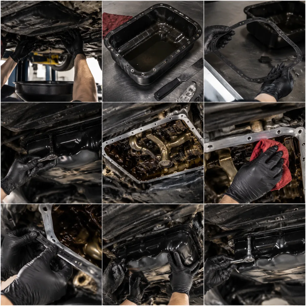
Step-by-step: oil pan gasket how to replace without creating a comeback
Follow the vehicle service information for lifting points, component removal, tightening sequence, sealant positions, and torque values. The workflow below is a professional baseline for typical passenger car and light commercial oil pan gasket replacement.
1. Prepare the vehicle and drain the oil. Disconnect the battery where required. Raise and support the vehicle safely. Drain the engine oil into a clean pan for at least 10 minutes. Check for metal particles, coolant contamination, heavy sludge, or silicone debris. 2. Remove access-blocking parts. Depending on the platform, remove undertrays, splash shields, exhaust brackets, engine mounts, crossmembers, starter shields, transmission stiffening plates, or steering and suspension parts. Support the engine if the service procedure requires it. 3. Loosen fasteners evenly. Break pan bolts loose in a controlled sequence, commonly from the outside toward the center unless service data says otherwise. Do not pry against machined sealing faces. Use designed separation points if provided. 4. Lower the pan carefully. Keep dirt, old gasket pieces, and sealant fragments out of the crankcase. If the oil pickup is visible, inspect the screen. RTV fragments, sludge, or metal debris are not normal; investigate before closing the engine. 5. Clean the sealing lands. Remove old gasket material with plastic or non-marring tools and approved cleaner. The surfaces should be dry to the touch before assembly. Do not gouge aluminium or leave abrasive residue. 6. Measure before reinstalling. Check the pan flange across bolt holes, corners, and long sides with a straightedge and feeler gauges. Look for pulled bolt holes, cracks, corrosion, and damaged threads. Chase dirty threads. Repair stripped holes only with an approved method and only where the service procedure permits it. 7. Fit the new gasket. Confirm orientation, locator tabs, bolt-hole alignment, oil passage cut-outs, and sensor clearances. Apply sealant only where specified, often at timing cover transitions, rear seal carrier joints, or defined corner joints. 8. Start bolts by hand. Each bolt should engage for at least 2–3 turns before tools are used. Cross-threading at this stage can destroy clamp consistency. 9. Tighten in stages. Use the specified sequence and calibrated torque tools. If exact data is unavailable, stop and obtain it. As a reference only, typical M6 oil pan bolts may be around 8–12 N·m and M8 bolts around 18–25 N·m; OE data overrides these examples. 10. Refill and run. Install a new drain plug washer where required. Refill with the specified oil grade and quantity. Start the engine and confirm normal oil pressure warning behavior within the expected time. 11. Inspect after heat and load. Check the flange, drain plug, timing cover area, rear seal area, and nearby components after idle, then again after 10–15 km or an equivalent thermal cycle.
Do not use impact tools for final tightening. Excess torque can split rubber beads, crush carrier gaskets, distort cork-rubber materials, or pull threads from aluminium blocks. Under-torque is just as damaging because clamp load becomes too low at corners and cover transitions.
Release checklist: what must be dry, recorded, and rechecked
A dry idle inspection is useful, but it is not enough. Oil behaves differently when hot, aerated, and moving under braking or cornering. Treat release inspection as part of the repair, especially on fleet vehicles and warranty-sensitive jobs.
Before the vehicle leaves the bay, verify:
Oil level is confirmed after filling, filter priming, and short run time; wait 3–5 minutes before final dipstick or electronic level confirmation where applicable.
No leakage is visible at the drain plug, pan flange, timing cover joint, rear main seal area, oil filter housing, oil cooler, or pressure sensor after idle and road-load.
The oil pan has proper clearance from the exhaust, subframe, steering components, and undertray after reassembly.
All shields, brackets, mounts, and fasteners removed for access are refitted.
No warning lamps, abnormal oil pressure behavior, or unusual engine noises appear after restart.
Fasteners are marked, recorded, or audited where workshop policy requires torque verification. Many shops use 100% checks for first jobs, then reduce checks after process stability is proven.
The customer, fleet, or warranty record includes mileage, installation date, part number, supplier, and part lot number.
For distributors, this checklist can become a printed or QR-linked installation sheet packed with the gasket. Good instructions reduce two common claim drivers: dry installation where sealant is required, and excessive sealant where the gasket should be installed dry or with only small dabs. Driventus can support application-specific notes, fitment labels, QR/barcode labeling, and carton-level traceability for large programs listed in our catalog.
Spec deep-dive: how buyers should compare oil pan gaskets
Two gaskets can look identical in a catalog image and behave very differently on the engine. The buying decision should not stop at outline shape and price. A 0.5 mm bolt-hole offset, uneven bead height, poor rubber recovery, or folded packaging can move clamp load away from the intended sealing path.
Compare suppliers on these points:
Dimensional control: Inspection against approved drawings, master samples, or customer CAD data. Common profile tolerances may be ±0.20–0.50 mm, with tighter limits on critical holes where required.
Material definition: State the compound family rather than accepting vague descriptions. ACM, FKM, NBR, silicone, cork-rubber, and metal/rubber constructions suit different heat, oil, and compression requirements.
Hardness control: Use Shore A testing with a defined tolerance, such as nominal ±5 points, instead of open-ended acceptance.
Compression set: Agree test temperature, duration, fluid exposure, and acceptance limit before purchase. This is central to long-term sealing after heat cycles.
Oil and heat ageing: Validate with fluids and temperatures relevant to the application, for example engine oil exposure at 125–150°C for high-temperature zones where applicable.
Bead geometry: Control bead height, parting lines, flash, and carrier finish. Bead-height variation directly changes local clamp load.
Hole and cut-out accuracy: Bolts should pass freely without forcing the gasket out of position. Oil passages, sensor openings, and corner transitions must match the application.
Packaging: Prevent kinking, bead compression, contamination, mixed applications, and ozone exposure. Flat gaskets should not be folded just to reduce carton size.
Traceability: Link lot code to production date, material batch, inspection records, mould or cavity identification where relevant, and packing records.
Driventus manufactures engine sealing parts under a documented quality system aligned with IATF 16949:2016 and ISO 9001:2015. For regulated markets, buyers may also request material declarations relevant to REACH (EC) No 1907/2006. These references do not replace application validation, but they give sourcing teams a stronger basis for supplier audits, PPAP-style documentation where required, and incoming inspection plans.
Failure modes: why a new oil pan gasket leaks again
When a repaired pan leaks again, the gasket is only one suspect. A useful review covers the installation method, engine condition, mating parts, storage history, and application selection. For fleets and repair chains, the cost is bigger than the gasket: technician time, replacement oil, vehicle downtime, warranty handling, and customer dissatisfaction.
Common repeat-leak patterns include:
Over-tightening: The sealing bead is crushed, split, or squeezed away from the sealing path. Shiny flattened rubber around every fastener often points to excess clamp load or the wrong tightening sequence.
Under-tightening: Clamp load is too low, especially at corners and cover transitions. Random loose bolts may indicate dirty threads, wrong bolts, missing staged tightening, or no torque tool.
Contaminated surfaces: Oil film, old RTV, corrosion, or abrasive residue prevents sealing. Aluminium grooves deeper than light staining should be assessed before reuse.
Wrong sealant location: A thick continuous bead can hold the gasket off the flange or break loose into the oil system. A 5–6 mm bead where only 2–3 mm corner dabs are specified creates both leak risk and oil pickup risk.
Bent pan flange: Prior over-tightening or incorrect removal can pull bolt holes upward. Local distortion over about 0.15–0.20 mm should be corrected or the pan replaced unless OE data allows otherwise.
Blocked PCV system: Excess crankcase pressure can force oil past a correctly installed gasket.
Incorrect application: Similar pans may differ by gasket thickness, bolt pattern, bead design, sensor cut-out, sump depth, or production-date split.
Damaged packaging or storage: Folded, compressed, ozone-exposed, heat-aged, or contaminated gaskets may not recover to their intended shape. Warehouses should avoid heat sources and heavy stacking on soft molded beads.
For importers and program managers, claim review should request photos of the cleaned flange, removed gasket, bolt condition, packaging label, installation date code, and mileage at failure. That evidence separates part nonconformity from procedural error and gives the factory enough information to act.
Frequently asked questions
Time varies by engine layout and access. Simple exposed pans may take 1–2 hours, while vehicles requiring crossmember, exhaust, engine mount, or transmission bracket removal can take 4–8 hours or more. Professional estimates should follow the vehicle service information and include cleaning, flatness inspection, torque work, oil refill, and post-repair leak testing.
No. Some designs require a dry gasket, while others require small RTV beads only at timing cover transitions, rear seal carrier joints, or specified corners. Excess sealant can detach and restrict the oil pickup screen. Always follow the application-specific service procedure and let RTV skin or cure according to the sealant maker’s timing before oil exposure where specified.
Yes. Driventus supplies engine sealing components for aftermarket distributors, wholesalers, OEM/Tier-1 projects, and repair chains. Typical program discussions cover drawings, samples, material choice, inspection criteria, packaging, labeling, validation requirements, MOQ, batch traceability, and lead time; final price and MOQ depend on tooling status, material, annual volume, packaging complexity, and documentation level.
For application lists, drawings, samples, MOQ, lead time, or batch pricing, please contact Driventus to request a quote through /contact.html