Crankshaft How to Replace: Procedure and Checks
Replacing a crankshaft is not a generic swap; it is a controlled engine decision. The right part depends on engine code, stroke, thrust layout, journal grade, oilway pattern, balance, and whether the shaft is new, remanufactured, or matched through an OE-style cross-reference such as an 06A… reference. The risk is simple: a crankshaft can look correct and still fail on dimensions, balance, hardness, lubrication geometry, or durability evidence.
Driventus is an independent aftermarket manufacturer; brand names and OE references are used for fitment identification only. This guide treats crankshaft how to replace as a decision chain: identify the correct specification, remove and inspect the failed part, install with measured clearances, then verify the result. It also covers the buyer side that often determines success or failure in real orders: drawing tolerances, incoming inspection, MOQ, lead time, packaging, and traceability. Quality systems and compliance frameworks such as IATF 16949:2016, ISO 9001:2015, REACH (EC) No 1907/2006, and relevant durability or emissions-related test methods can support purchasing decisions, but they do not replace engine-specific measurement before assembly.
Start with the fitment decision, not the catalog number
Before approving a replacement crankshaft, confirm the application from the engine code, VIN/build data, market version, and transmission type rather than relying on a broad model listing. Similar engines can use different bearing classes, strokes, thrust arrangements, reluctor patterns, rear flanges, or oil drilling layouts. One common sourcing error is assuming that a shared OE-style 06A… reference means every variant is interchangeable.
Use this checklist before issuing a purchase order:
- Engine code, displacement, build year, market version, and emission level
- Standard, undersize, or oversize strategy for journals and bearings
- Main journal diameter, width, bearing grade, and tolerance band
- Rod journal diameter, width, crankpin offset, and fillet radius
- Stroke, counterweight profile, and crankpin position
- Number, position, and style of thrust faces or thrust washers
- Trigger wheel, tone ring, keyway, spline, flange, pilot bore, or drive-end features
- Oil gallery drilling pattern, cross-drilling, chamfer size, and plug configuration
- Required material, heat treatment, hardness range, hardened depth, and journal surface finish
- Dynamic balance requirement and whether flywheel, damper, pulley, or clutch components are matched
- Packaging method, rust protection period, carton/crate dimensions, and inspection documents required at shipment
For many light-vehicle crankshafts, drawing tolerances are commonly controlled in the micrometre range: journal diameter may be specified within roughly 0.005–0.020 mm depending on design, out-of-round and taper may be limited to about 0.003–0.010 mm, and runout at key journals may be held around 0.02–0.05 mm. Do not treat these as universal limits; use the engine drawing, service manual, or supplier-approved specification.
For purchasing teams, a dimensional report is more useful than a generic fitment note. Ask for inspection data against the drawing or validated specification, not only part-number mapping. A practical incoming-control plan for repeat orders is: 100% visual check of packaging and rust protection, 100% part-number/marking verification, and AQL or fixed-sample measurement of main journals, rod journals, runout, thrust width, flange dimensions, and oil-hole cleanliness. If the application is turbocharged, high-load, fleet, or commercial duty, confirm material certification, fatigue-test evidence where available, and the supplier’s quality documentation. See our catalog for related engine parts and quality system details.
Strip the engine with the failure in mind
A reliable replacement begins with controlled teardown. Drain the oil, remove ancillary drive components, and strip the engine in a clean work area. Use lint-free wipes, clean trays, and separate labelled bags for main caps, rod caps, bearing shells, thrust washers, bolts, spacers, dowels, and oil gallery plugs. Cap location and orientation are critical; mixing caps or reversing them can distort the main bore, reduce oil clearance, and damage the replacement shaft during the first rotation.
Inspect the removed crankshaft before disposal or core return. Look for:
- Scoring, pitting, wiping, or smeared bearing material on main and rod journals
- Blueing, heat tint, or darkened oil residues that indicate oil-film failure
- Cracks around fillets, oil holes, keyways, counterweights, and flange areas
- Fretting, step wear, or polished bands at thrust surfaces
- Embedded debris marks from contaminated lubricant or failed oil filtration
- Edge loading or one-sided wear that suggests misalignment or bent rods
- Damaged threads, dowel holes, pilot bores, reluctor teeth, or seal tracks
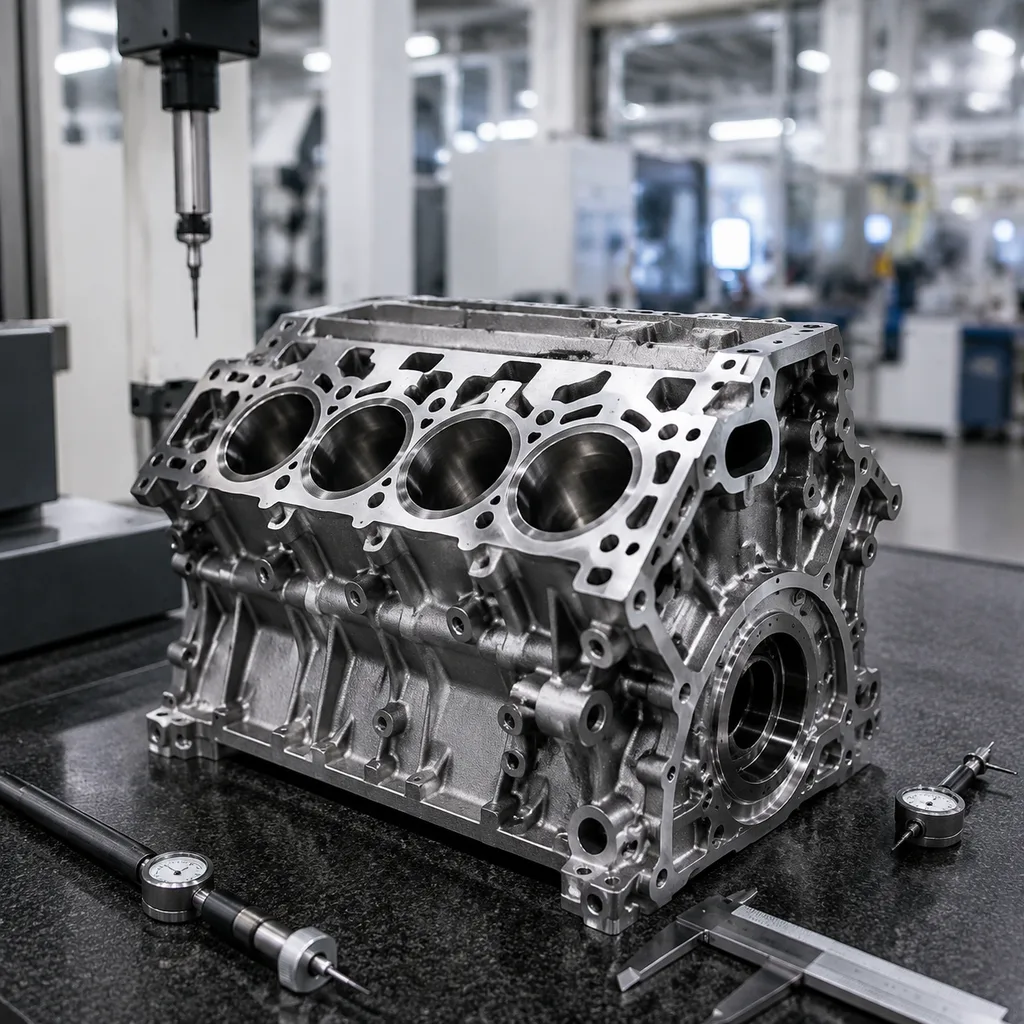
Measure the journals with a calibrated outside micrometre, not a vernier caliper. Take readings at minimum two positions along each journal and at 90° rotation to capture taper and out-of-round. Record main and rod journal diameters to 0.001 mm or 0.0001 in where the instrument supports it. Check crankshaft runout on V-blocks or between centres with a dial indicator, and compare against the engine specification. Also inspect the block main tunnel with a bore gauge if bearing damage is uneven; a new crankshaft will not correct a misaligned block.
Check the bearing shells as evidence. Copper exposure, overlay fatigue, debris tracks, crushed edges, blackened backs, and polished parting-line areas can point to lubrication failure, detonation, poor cap seating, distorted rods, blocked galleries, or contaminated oil. If the old crankshaft shows heavy wear in one location, the root cause may be block tunnel alignment, oil pump performance, blocked galleries, rod distortion, or contaminated oil rather than the shaft alone. That diagnosis matters when choosing a standard replacement, undersize bearing strategy, remanufactured unit, or custom specification through custom manufacturing.
Install in sequence, and stop when the feel changes
The installation process should be clean, measured, and repeatable. Wash the block, brush every oil gallery, flush with clean solvent, blow dry with filtered compressed air, and verify that gallery plugs, dowels, and threaded holes are secure and free of debris. Any abrasive media left after machining can destroy new bearings within minutes. Dry-fit the correct bearing shells and measure oil clearance using the workshop-approved method for that engine family. Do not substitute a generic bearing set when validating a production replacement; clearance must be checked with the intended shells and caps.
Common passenger-car oil-clearance ranges are often around 0.025–0.060 mm for main and rod bearings, while heavier diesel or performance engines may use different targets. Thrust end play may commonly fall around 0.07–0.30 mm, depending on design. These numbers are reference ranges only; the service specification is the controlling document. Use a dial indicator for end play, a bore gauge plus micrometre for bearing clearance where possible, and plastigage only as a secondary workshop check. Record all readings before final closure.
Apply the correct assembly lubricant to main journals, rod journals, and thrust surfaces, then lower the crankshaft into place without forcing it. Avoid touching finished journals with dirty gloves or resting the shaft on unprotected surfaces. If fasteners are torque-to-yield, replace them; reused stretched bolts can change clamp load and bearing crush.
Practical sequence
1. Confirm crankshaft part number, journal size, oil-hole layout, reluctor/trigger pattern, flange, and pilot dimensions before installation. 2. Install main bearings and thrust components dry in their saddles, ensuring tangs are seated and oil holes align. 3. Lubricate journals and thrust faces, set the crankshaft into the block, and confirm smooth hand rotation before cap torque. 4. Install main caps in original locations and torque in the specified order, stages, and angle; mark completed fasteners. 5. Measure crankshaft end play with a dial indicator and record the value. 6. Fit piston and rod assemblies, torque rod fasteners, and recheck rotation after each cylinder or pair. 7. Confirm timing-drive, rear flange, trigger, front seal, rear main seal, and damper interfaces before final closure. 8. Prime the lubrication system until oil reaches galleries and pressure is visible where the engine design allows.
Typical acceptance targets depend on the engine family, but the practical requirement is consistent low-friction rotation with no tight spots and no metal-to-metal noise. Turning torque should increase predictably as seals and piston assemblies are added; a sudden increase after one cap or rod is a stop point. If the shaft binds after cap torque, stop. Recheck bearing seating, cap orientation, main bore alignment, thrust washer placement, journal dimensions, and fastener condition before assuming the new component is defective.
Compare the shaft against the spec sheet, not the photos
A crankshaft replacement should be matched by geometry, metallurgy, finish, and validation evidence—not by external appearance alone. The following fields should be verified on a purchase order, supplier drawing, PPAP-style file where used, or incoming inspection sheet.
| Check item | What to confirm | Practical target or evidence | Why it matters |
|---|---|---|---|
| Main journal size | Diameter, width, roundness, taper | Drawing tolerance; often micrometre-level control | Bearing fit and oil-film stability |
| Rod journal size | Diameter, width, crankpin offset, fillet radius | Confirm standard/undersize grade before bearing order | Rod alignment, clearance, and piston travel |
| Stroke | Nominal value and tolerance | Compare to engine family; do not infer from model name | Compression ratio, piston position, and engine behavior |
| Runout | Centreline straightness at journals/flange | Usually checked with dial indicator on V-blocks or centres | Vibration, seal wear, and bearing load |
| Thrust location | One-side, central, or application-specific thrust design | Verify thrust width and washer arrangement | Axial control under clutch or converter load |
| Material | Forged steel, cast steel, nodular iron, or specified alloy grade | Mill certificate or heat/lot traceability | Fatigue strength and durability margin |
| Heat treatment | Induction/nitriding process, hardness, case depth | Hardness map or batch report where required | Wear resistance and journal life |
| Surface finish | Journal roughness and fillet finish target | Typical Ra may be about 0.10–0.30 µm for journals, specification dependent | Bearing life, oil retention, and stress concentration control |
| Dynamic balance | Residual imbalance limit and method | State g·mm limit, rpm, and whether external parts are included | Vibration control and bearing load reduction |
| Oil passages | Drilling layout, chamfering, plug security, cleanliness | Bore-scope/airflow/flush record for production lots | Lubrication reliability at start-up and load |
| Interface features | Flange, keyway, gear, trigger, seal track, pilot bore | Measure mating diameters and tooth/index location | Correct assembly with timing and driveline components |
| Packaging | Rust inhibitor, journal sleeves, supports, desiccant, crate strength | Salt-spray/storage expectation or corrosion-free arrival requirement | Prevents transit damage and rejected receipts |