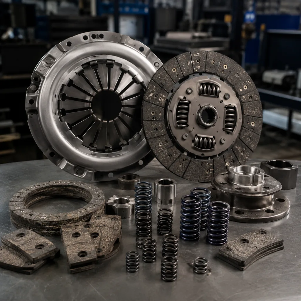
Clutch kit material selection is a warranty decision, not just a sourcing line item. The wrong facing, spring curve, pressure-plate finish or bearing grade can pass a fitment check and still create chatter, slip, noise, short wear life or corrosion claims after sea freight. For B2B programs, approve the kit as a controlled system: friction formulation, metallurgy, dimensions, inspection method, packaging route and lot traceability all need defined limits. A complete kit usually includes the cover assembly, pressure plate, driven disc, release bearing, pilot bearing where applicable, alignment tool and hardware. Driventus manufactures engine and powertrain components in Taizhou, Zhejiang, and supports aftermarket distributors, OEM/Tier-1 sourcing teams and repair-chain purchasing groups. Production is managed under IATF 16949:2016 and ISO 9001:2015. Driventus is an independent aftermarket manufacturer; brand names are referenced for fitment only.
Decision framework: approve the kit as a system
Do not start with the friction label. Start with the duty cycle. A clutch kit is a matched system: the driven disc transmits torque and damps torsional vibration, the cover assembly holds clamp load through heat cycles, and the bearings manage axial load, contamination risk and grease stability. If one item is downgraded, the full kit behavior changes.
A useful RFQ should lock these inputs before price discussion: rated engine torque, disc outside diameter, spline count, cover bolt pattern, bearing type, target market, expected use case and packaging route. Then review the bill of materials by function.
Component
Common material basis
Practical specification points
Friction facing
Organic composite, ceramic-metallic blend, copper-free or low-metallic formulation
Static/dynamic μ target, often 0.28–0.42 for organic passenger-car facings; thickness tolerance commonly ±0.10–0.20 mm; burst speed requirement
Axial clearance, grease fill, sealing, rotational noise, carrier fit
</tr></thead><tbody> </tbody></table>This system view prevents a common sourcing error: approving the visible clutch kit material while leaving the bearing, spring, coating or carton underdefined. For sourcing comparison, distributors can review our catalog to map kit families by vehicle segment, engine torque range and regional demand.
Friction facing comparison: smoothness, heat and wear
The facing is the most visible clutch kit material choice, but it cannot be specified alone. It works against the pressure plate and flywheel, under a defined clamp load, with rivet support and disc runout limits. A high-friction compound can still fail early if the mating surface is too rough. An aggressive material can solve slip and create new claims for judder, noise or flywheel wear.
Organic composite facings suit many passenger car and light commercial vehicle aftermarket kits. They typically combine fibre reinforcement, resin binder, friction modifiers and metallic fillers. Normal B2B targets may include stable μ in the 0.28–0.40 range, smooth engagement, moderate noise and controlled flywheel wear.
Ceramic-metallic facings belong in a narrower decision box: higher torque, towing, fleet duty or severe-service use. They can raise torque capacity and heat resistance, often with working-temperature capability above organic facings. The trade-off is harsher engagement and potentially faster mating-surface wear if the cover assembly, flywheel finish and driver profile are not matched.
Specify the facing by performance window, not by a loose label:
Static and dynamic coefficient of friction range, including hot test and recovery result.
Maximum operating temperature, for example 250–350°C for many organic applications and higher for ceramic-metallic programs, subject to formulation.
Facing thickness tolerance under the approved drawing or sample, commonly controlled within ±0.10–0.20 mm.
Disc burst speed test result, with safety margin above maximum engine speed and customer requirement.
Rivet pull-out strength, facing shear strength and rivet head height after assembly.
Wear rate after defined cycle test, not only visual condition after bench running.
Compliance status for REACH (EC) No 1907/2006 where applicable.
For EU and UK importers, material declarations should be requested before sample approval because friction formulations may include regulated substances. Driventus can support application-specific formulation review through custom manufacturing when the buyer provides torque target, usage profile, destination market and restricted-substance requirements.
Spec deep-dive: spring, plate and hub controls
The metal parts decide whether the approved facing can do its job. They control clamp force, release feel, dimensional interchangeability and high-speed stability. Small deviations here can look harmless on a bench and become field complaints after installation.
The diaphragm spring is normally produced from heat-treated spring steel, with controlled hardness and shot-peening or stress-relief steps where specified. Ask for clamp load at installed height, the full release load curve and post-fatigue retention. A single load number is not enough. Pedal force, release travel and friction torque depend on the curve. For many aftermarket programs, clamp-load tolerance is controlled as a percentage band around the approved sample or drawing target, commonly ±5–8% unless the customer specification is tighter.
The pressure plate is generally cast iron or steel. Cast iron offers thermal mass and machinability for many replacement applications. Steel may be selected where weight, strength or manufacturing route requires it. Key controls include parallelism, contact surface roughness, hardness and dynamic balance. Surface roughness should be defined on the drawing or approved sample; Ra 1.6–3.2 µm is a common practical range for many machined contact faces. Too rough, and the facing wears fast. Too polished, and bedding or initial bite can shift. Pressure plate runout is often controlled within 0.05–0.15 mm depending on diameter and application.
Hub splines need gauge control, not only visual inspection. A disc can look acceptable and still cause installation complaints if the spline profile is tight, undersized or misaligned with disc runout. Confirm these controls before approval:
Input shaft go/no-go gauge compatibility for each application and spline lead-in burr control.
Hub spline hardness and case depth where heat treatment is used, with test location defined.
Disc axial runout and lateral runout limits, commonly ≤0.50–0.80 mm at the facing OD for many passenger applications.
Torsion spring free length, load, color/grade identification and seating condition after riveting.
Cover bolt-hole positional tolerance against fixture, with production fixture calibration frequency.
Dynamic balance grade or unbalance limit where required for high-speed or NVH-sensitive kits.
For OE part-number cross-reference programs, references should rely on buyer-supplied application data and generic catalogue mapping, for example OE 06A… or OE 11251… where already present in the customer’s interchange file. Driventus does not claim vehicle manufacturer approval or endorsement.
Validation checklist: turn samples into production controls
A clutch kit material specification only matters if production can repeat it. Treat the approved sample as the baseline, then convert it into a control plan with inspection frequency, sampling method, acceptance limits and reaction plan. Supplier comparison should include material certificates and functional test data, especially for high-rotation SKUs or applications with known warranty sensitivity. Driventus manages production controls under its quality system, aligned with IATF 16949:2016 and ISO 9001:2015.
Parameter
Typical control method
Actionable buyer target
Cover assembly clamp load
Load test at installed height
Drawing target with ±5–8% tolerance or agreed customer range
Pressure plate runout
Dial indicator or automated fixture
Often ≤0.05–0.15 mm depending on diameter
Disc runout
Rotational fixture check
Commonly ≤0.50–0.80 mm at facing OD unless drawing differs
Balance
Dynamic balancing where specified
Define g·mm limit or balance grade by application speed
Facing thickness
Micrometer or vision system
Commonly ±0.10–0.20 mm per facing or per assembled disc requirement
Bearing noise
Rotational noise test
Noise/roughness limit agreed from master sample; reject abnormal vibration or grease leakage
Coating thickness
Gauge or salt spray validation
Zinc/phosphate/coating thickness and salt-spray hours agreed by route and storage time
</tr></thead><tbody> </tbody></table>Relevant standards may include IATF 16949:2016 for automotive quality management, ISO 9001:2015 for quality management systems and REACH (EC) No 1907/2006 for chemical compliance in applicable markets. Test methods should be defined in the control plan, customer drawing or mutually approved inspection specification, not assumed from a catalogue phrase.
For new suppliers, request PPAP-like evidence where appropriate: process flow, PFMEA, control plan, dimensional report, material report, functional test report and packaging approval. For repeat orders, require shipment inspection records tied to lot number. A recycled sample report does not prove the current batch.
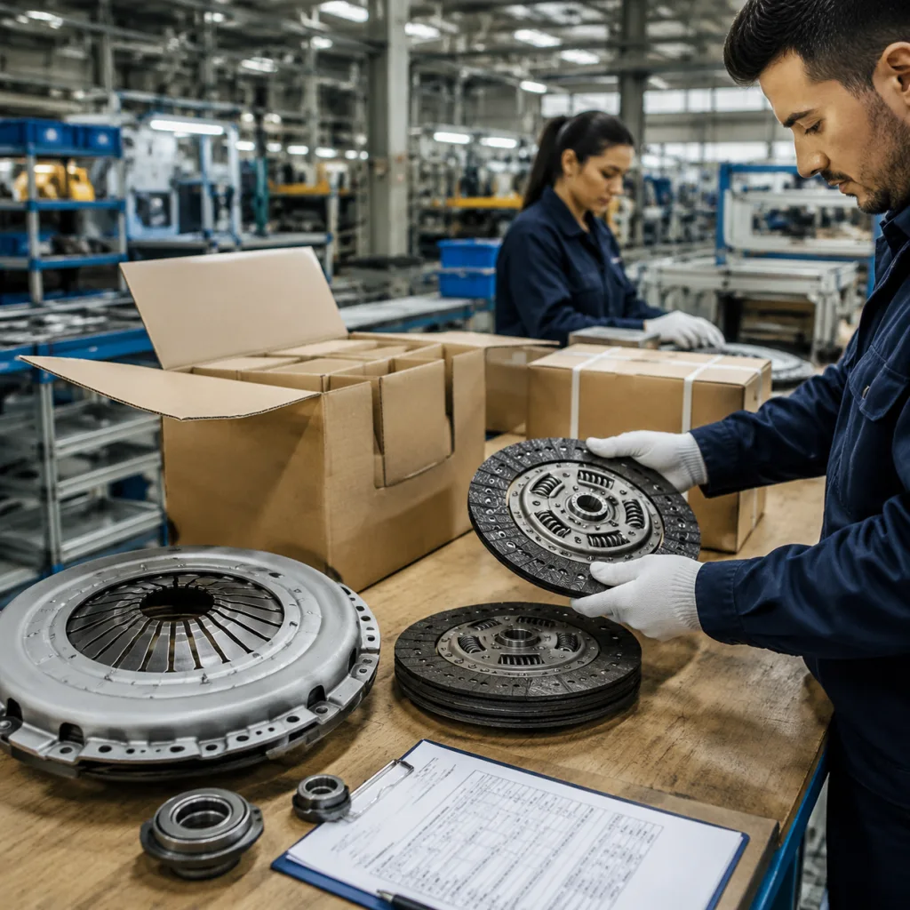
Failure modes after production: packing, traceability and documents
Many clutch kit claims start after the parts leave the line. Mixed kits. Wrong release bearings. Rust on machined faces. Oil transfer onto facings. Missing country-of-origin fields. These are not minor admin issues; they can block incoming inspection or create installation failures.
Packaging must protect machined surfaces, prevent disc contamination and keep the release bearing matched to the correct application. Friction facings should not contact oil, corrosion inhibitor or loose abrasive packaging material. Validate the carton against the real route: inland truck handling, container humidity, pallet stacking height and final warehouse storage time.
A practical import specification should require:
Individual kit label with part number, batch number, production date and country-of-origin field.
Component-level traceability for friction disc, cover and release bearing, with lot code readable after unpacking.
VCI paper, bagging or equivalent corrosion protection for machined metal surfaces where suitable, separated from friction material.
Carton drop-test requirement based on shipping route and pallet pattern, commonly 60–80 cm for export cartons where agreed.
Barcode or QR code format agreed before mass production, including EAN/UPC or buyer SKU where required.
English product label plus destination-market label fields, warning text and recycling marks where required.
Certificate of conformity, packing list, commercial invoice data, HS code confirmation and inspection report for each shipment.
For distributors, private-label packaging can be supplied after artwork approval, carton strength confirmation and first-article packing sign-off. For OEM/Tier-1 and repair-chain programs, Driventus can align inspection reports with incoming quality requirements, including AQL sampling or customer-specific control plans. A common approach is AQL 1.0–2.5 for major defects and tighter controls for fitment-critical dimensions, but the final level should match order value, field risk and buyer policy. Driventus is an independent aftermarket manufacturer; brand names are referenced for fitment only.
Quotation scenario: when the cheapest offer is not comparable
Two clutch kit quotes can show the same application and very different risk. One may use a lower-cost facing formulation, a different bearing grade, wider spring heat-treatment tolerance, looser machining control or weaker export packaging. If kit content and inspection rules differ, the price comparison is invalid.
Build the quotation grid around identical requirements. Separate part cost, packaging cost, tooling or fixture cost, sample cost, freight term, MOQ, lead time and validity period. Then ask each supplier to quote against the same drawing, inspection standard and kit content list.
Before approval, request:
Full kit content list with component photos, key dimensions, bearing type and spline specification.
Material description for friction facing, pressure plate, diaphragm spring and hub, including any restricted-substance statement.
Clamp load curve, disc runout data, bearing noise data and facing thickness data from recent production.
Sample inspection report, batch traceability format and reaction plan for nonconforming lots.
MOQ, lead time, tooling status, sample schedule and packaging terms.
Compliance statement for REACH (EC) No 1907/2006 where applicable.
Warranty return analysis procedure, 8D or corrective-action format and expected response time.
Review MOQ and price logic by SKU family. Existing-tooling aftermarket SKUs normally support lower MOQ and faster lead time than new developments. Mixed-SKU trial orders may be practical for market validation. Custom friction formulation, private-label cartons or new pressure-plate tooling usually raise MOQ.
As a working B2B planning range, stocked or current-production samples may take about 7–15 days. Existing-tooling production often takes about 30–45 days after deposit and artwork approval. New-tooling or custom-material programs may require about 60–90 days depending on validation scope. Final MOQ and lead time depend on application range, material selection, packaging complexity and inspection requirements.
For multi-SKU programs, start with high-rotation applications and validate fitment, pedal feel, engagement quality and bearing noise under controlled installation conditions. After approval, extend the same clutch kit material and inspection rules to long-tail SKUs so the program remains consistent as coverage expands. Buyers can request a quote with target applications, annual volume, required packaging and destination market.
Frequently asked questions
Organic composite friction facings are common for passenger car aftermarket programs because they balance engagement smoothness, wear rate and cost. Typical targets may include stable friction performance around μ 0.28–0.40, controlled thickness tolerance and low flywheel aggression. Higher-torque, towing or severe-service applications may need ceramic-metallic compounds. The correct choice depends on vehicle torque, driving profile, pressure plate finish, clamp load and warranty expectations.
Request the kit bill of materials, drawing or approved sample reference, material description, clamp load curve, disc runout data, facing thickness data, bearing inspection data, packaging specification, traceability format and compliance statement for applicable markets such as REACH (EC) No 1907/2006. For new programs, also request process flow, control plan, dimensional report and sample approval record.
Yes. Driventus supports B2B clutch kit programs with agreed specifications, packaging artwork, inspection reports and traceability requirements. MOQ and lead time depend on application range, tooling status, clutch kit material selection and packaging complexity. Existing-tooling programs are generally faster than custom-material or new-tooling programs, which require additional sample and validation time.
For application mapping, clutch kit material review or private-label sourcing, send drawings, target OE cross-references, annual volume, target MOQ, packaging requirements and destination market to Driventus. Contact us at /contact.html