Camshaft for Nissan Rogue Replacement: Buyer Approval Framework
A camshaft for Nissan Rogue replacement should not be approved from a catalog line alone. The part has to reproduce valve motion, timing signals, oil-feed behavior, thrust control, and wear performance in the exact Rogue engine application. On QR25DE and related platforms, small differences in base circle, lobe lift, sensor target angle, phaser oil-feed alignment, or journal runout can show up as unstable idle, timing faults, emissions readiness problems, noise, oil-film failure, or early wear.
Treat the purchase as an engineering release. Confirm engine code, cam position, valve-train layout, journal geometry, lobe profile, timing interface, surface finish, and heat-treatment condition before volume stock. Typical procurement targets may include journal diameters controlled within drawing limits of about +/-0.010 to +/-0.020 mm, total indicated runout near 0.03 mm or better on supported journals, and verified surface roughness on lobes and journals. Final acceptance values must come from the approved drawing, master sample, or OE benchmark for the exact engine code and cam position.
Driventus supplies engine and powertrain parts for B2B buyers in multiple regions, building to published specifications, approved samples, and customer drawings rather than broad catalog descriptions. Driventus is an independent aftermarket manufacturer; brand names are used only for fitment identification. Use this guide to structure approval checks, test requests, MOQ and lead-time assumptions, and supplier questions before placing an order.
Fitment Decision: What Has to Match Before Anything Else
Start with a strict fitment decision, not a loose application match. A replacement camshaft is a precision valve-train component. It must match the engine architecture and timing system closely enough to reproduce the intended valve motion and sensor signals.
For Nissan Rogue applications, fitment depends on model year, market, engine variant, and whether the camshaft is for the intake or exhaust side. A procurement file should include the VIN or full vehicle description, engine code, OE reference where available, and measured data from the removed component, an approved sample, or service documentation. For common Rogue sourcing work, separate files by generation, market, engine code, intake/exhaust position, and timing-control hardware. Do not combine lines only because the catalog says "2.5L".
Minimum match points include:
Journal count, journal diameter, width, and spacing, measured at multiple clock positions for ovality and taper
Overall length, thrust face position, and end-play control surfaces
Lobe lift, base circle, duration profile, ramp form, and phasing relationship between lobes
Cam sensor trigger or reluctor feature location, including angular position relative to a datum
Oil passages, locating features, plugs, grooves, and assembly marks where applicable
Surface hardness and finish on journals, lobes, thrust faces, and high-contact edges
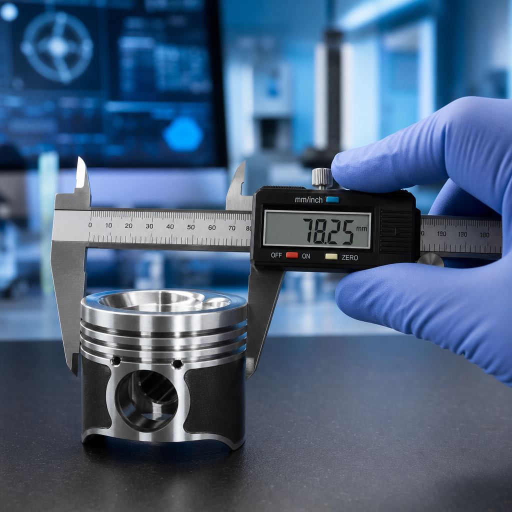
A practical incoming check records journal diameters with a micrometer to 0.001 mm resolution, lobe lift from base circle to nose, overall length, thrust width, runout between centers or V-blocks, and sensor-target angle from the agreed datum. A wrong feature may not stop installation. It may fail later through noise, fault codes, unstable idle, emissions nonconformity, abnormal wear, or repeat repair claims.
Where OE-Equivalent Claims Usually Break Down
OE-equivalence means the replacement follows the same functional geometry and material performance as the original component. It does not mean the supplier copied a vehicle listing or used a loose interchange table. For a Nissan Rogue camshaft, common mistakes include engine-family confusion, intake-versus-exhaust mix-ups, phaser changes inside a model range, and assumptions based on model year alone.
Use this comparison list during approval:
Check item
What to verify
Buyer target before release
Engine code
Exact engine variant and market application
VIN/application evidence plus OE or validated interchange
Camshaft position
Intake, exhaust, or matched pair
Position marked on drawing, label, and packing list
Sprocket or phaser interface
Bolt pattern, keyway, seat, oil feed, locating features
100% visual check plus dimensional confirmation on samples
Journal geometry
Diameter, width, spacing, thrust control
Drawing tolerance, commonly +/-0.010 to +/-0.020 mm where specified
Lobe profile
Lift, base circle, ramp shape, duration
Profile overlay or CMM/cam doctor report against master sample
Sensor target
Trigger wheel, reluctor, or machined timing feature position
Angular position verified from agreed datum, not judged visually
Surface condition
Roughness, hardness, coating if used, corrosion condition
Ra and hardness values stated by surface and measurement method
</tr></thead><tbody> </tbody></table>Ask suppliers for dimensional inspection reports, material certificates, and a clear cross-reference method. The offer should identify the data source: OE sample reverse engineering, customer drawing, licensed technical data, or buyer-approved golden sample. A camshaft offered without traceable inspection data should not be released for fleet, warehouse, or distribution use, even when the application text looks right.
Build an approval matrix with three columns: buyer requirement, supplier declared value, and measured sample value. Price-only comparison is weak. Two parts can share the same application label while differing in phaser oil feed, trigger position, or lobe ramp shape.
Spec Deep Dive: Material, Hardness, Finish, and Debris Control
Camshafts work under difficult lubrication conditions, especially at the lobe and follower interface and during cold starts. Material selection, hardening depth, surface finish, and cleanliness decide whether the part can survive long drain intervals, stop-start operation, and repair environments where residual debris may still be present.
Typical procurement requirements include:
Alloy cast iron, chilled cast iron, forged steel, or billet steel depending on the engine design and OE benchmark
Induction hardening, chill hardening, carburizing, nitriding, or another approved surface-hardening process where applicable
Controlled core hardness for fatigue resistance and dimensional stability
Lobe and journal surface hardness commonly specified in the HRC 50-60 range for hardened steel surfaces, or by HB/HV scale for cast materials, subject to drawing
Effective case depth or hardened layer confirmation, often specified around 1.0-3.0 mm for induction-hardened zones when the design requires it
Fine surface finish on journals, lobes, and thrust faces, with journals often targeted around Ra 0.2-0.4 micrometer and lobes around Ra 0.4-0.8 micrometer unless the drawing states otherwise
Crack control after heat treatment and machining
Anti-corrosion protection for storage, sea freight, and inland transport, typically VCI paper or bagging plus rust preventive oil for 6-12 months of protected storage
The supplier should disclose the base material grade, casting or forging route, hardening method, hardness range, case-depth requirement, and inspection method for lobe and journal surfaces. Hardness data must be tied to defined measurement locations. A useful report names the instrument, scale, load, test locations, and acceptance range.
Without these records, the buyer has little leverage during durability investigations. Driventus supports requests for technical drawings, PPAP-style document packs where required, and material traceability under a documented quality process. For higher-volume programs, request process control data for the casting or forging lot, heat-treatment batch, straightening operation, finish grinding, washing, rust prevention, and final inspection.
Validation Plan: From Bench Checks to Pilot Lot
Replacement parts should be validated before release into stock, especially for repair chains, fleet maintenance, and regional distribution. For a camshaft, validation has to combine dimensional, metallurgical, cleanliness, packaging, and functional checks. One good bench reading is not enough.
Recommended checks include:
1. Coordinate measuring machine inspection for critical dimensions and feature positions, including journal spacing, thrust faces, sensor target, and phaser interface 2. Runout measurement on supported journals, with a typical buyer limit near 0.03 mm TIR unless the approved drawing specifies another value 3. Surface roughness measurement on lobes, journals, and thrust faces, recorded as Ra or Rz with sampling length stated 4. Hardness testing at defined locations and, where needed, case-depth verification by sectioning or approved nondestructive method 5. Magnetic particle inspection, dye penetrant, or equivalent crack detection where applicable after heat treatment and straightening 6. Visual inspection for burrs, edge damage, corrosion, blocked oil passages, damaged plugs, and incomplete washing 7. Assembly trial with timing components, phaser hardware, fasteners, cam caps or bearing supports, and sensors 8. Engine or rig validation for noise, oil pressure, timing stability, cold-start behavior, hot idle, and fault-code behavior 9. Packaging validation for corrosion after humidity exposure or simulated transit, especially for sea freight lanes above 30 days
A practical approval route is 3-5 pieces for dimensional and metallurgical review, then a pilot lot of 20-50 pieces before warehouse release. For production lots, many buyers use AQL inspection: critical features at AQL 0 or 100% inspection, major defects around AQL 1.0, and minor visual defects around AQL 2.5. Match the exact sampling plan to warranty exposure and sales channel risk.
Published standards can support supplier-system and material-control reviews, including IATF 16949:2016, ISO 9001:2015, and REACH (EC) No 1907/2006 for restricted-substance compliance where relevant. If the replacement is sold into a regulated emissions market, align the approval plan with local requirements and vehicle platform documentation. A mechanically similar part can still be unsuitable if it changes timing behavior or diagnostic performance.
Repair Scenario: When Replacing the Camshaft Makes Sense
A camshaft replacement is justified when inspection confirms wear, scoring, seizure, lobe damage, timing-interface damage, oil starvation damage, or timing-related faults that remain after the rest of the system has been checked. It should not be the first part replaced without diagnosis.
Common indicators include:
Persistent cam correlation faults after timing chain, tensioner, guide, sensor, actuator, and phaser checks
Metal debris in the oil filter, sump, valve-train area, or oil-control valve screen
Lobe wear, pitting, scoring, heat discoloration, or abnormal contact pattern visible during valve cover inspection
Low compression, misfire, poor running, or unstable idle linked to valve timing loss
Excessive valve-train noise after lubrication problems, low oil pressure, or sludge contamination
The repair decision should also cover the timing set, lifters or followers, seals, oil control components, cam caps or bearing surfaces, and phaser-related parts if they show wear or contamination. Replacing only the camshaft while leaving damaged ancillary parts in service often creates repeat failure and warranty disputes. If the original failure involved debris, the repair process should include oil-system cleaning, filter replacement, sump inspection where practical, and verification that oil passages are clear.
For procurement teams supporting repair chains, the better target is a complete repair-kit strategy with controlled compatibility. That reduces variation across workshops and makes failure analysis easier than isolated line-item buying. A kit file should define which parts are mandatory, which are inspection-dependent, and which fasteners or seals are single-use according to the repair procedure.
Supplier RFQ Package: Data That Separates Good Quotes From Weak Ones
Send the same RFQ data request to every supplier. It forces the comparison onto engineering content, not only price and delivery. It also exposes hidden variation between samples, pilot batches, and volume shipments.
Required documents and data include:
Part number cross-reference and application list, separated by engine code, model year, market, and intake/exhaust position
Confirmed engine code, model-year range, camshaft position, and OE reference or buyer-approved interchange basis
Engineering drawing, dimensional summary, or approved-sample comparison with datum scheme
Material specification, casting or forging route, heat-treatment method, hardness range, and case-depth requirement if applicable
Inspection report for critical features, including journal diameters, runout, lobe lift, thrust width, overall length, and timing-interface dimensions
Surface finish requirement and measured results for lobes, journals, and thrust faces
Packaging specification, corrosion protection method, carton quantity, gross weight, pallet pattern, and label format
Lead time, MOQ, batch size, price break, and traceability method
Certificate references for the supplier quality system
Compliance declarations required by the destination market
Commercial data belongs in the technical decision. For standard replacement camshafts already tooled, a typical MOQ may be 50-100 pieces per part number, with 25-45 days production lead time after deposit and packaging approval. For new development or drawing-based production, expect tooling or fixture charges, 45-75 days for first samples, and 60-90 days for the first production lot after sample approval. Price usually moves with material route, heat treatment, finish grinding time, inspection level, packaging, and annual volume. A 100-piece order and a 1,000-piece annual program should not carry the same unit-cost expectation.
You can review our catalog for adjacent engine parts and our quality system for the controls used in production and inspection. For applications where drawing-based development is needed, custom manufacturing is available for customer-defined geometry and packaging requirements.
If the request is part of a larger engine program, buyers can also review engine components for related parts that should be validated together.
How Driventus Keeps Fitment Repeatable After Sample Approval
The difficult part is not producing one acceptable sample. It is keeping the measured behavior stable across batches. Replacement camshafts are produced through a controlled manufacturing flow that includes incoming material checks, process monitoring, heat-treatment control, final dimensional inspection, and batch traceability. Many fitment problems appear at the interfaces: journal alignment, thrust location, sensor timing, oil feed, and sprocket or phaser engagement.
Our replacement approach focuses on four points:
Dimensional match to approved reference geometry, including defined tolerances for journals, lobes, thrust faces, overall length, and timing features
Correct timing and sensor-interface relationship verified against a sample, drawing, or agreed datum
Consistent material and heat-treatment performance supported by batch records and inspection results
Packaging and corrosion control for export storage and transit, including individual protection for machined surfaces
A typical process route includes material receipt, blank casting or forging review, rough machining, heat treatment, straightening where required, finish grinding of journals and lobes, oil-hole and edge finishing, washing, rust prevention, final inspection, labeling, and packed batch release. At quotation stage, Driventus confirms whether existing tooling is available or whether sample-based development is required. That distinction affects price, MOQ, and timing more than the catalog name does.
For B2B buyers, the release question is simple: can the part move from sample approval to volume supply without changing its measured behavior? That standard guides quotation review, sample submission, and production release. For repeat orders, batch traceability should connect finished cartons to production date, inspection record, heat-treatment lot, and material lot.
If the buyer has a measured sample, drawing, OE cross-reference, or application file, Driventus can work against that data rather than relying on broad fitment descriptions. This helps separate a suitable camshaft for Nissan Rogue replacement from a part that only matches a catalog keyword.
Final Release Checklist Before Stocking
Before purchase approval, confirm the following:
Exact engine code, market, and model-year range, supported by VIN examples or OE cross-reference
Intake or exhaust position, or matched-set requirement, with labels and cartons marked accordingly
OE reference, approved sample, or drawing basis, including revision level and datum scheme
Critical dimensions, including journals, thrust faces, lobe lift, base circle, runout, and overall length
Sensor trigger location and sprocket, gear, or phaser interface, including oil-feed alignment where applicable
Required surface finish, hardness, hardening method, case depth, and coating if applicable
Inspection report format, sampling level, retained-sample rule, and batch traceability process
Country-specific compliance and documentation requirements
Repair-kit compatibility with timing, sealing, follower, oil-control, and phaser-related parts
MOQ, unit-price breaks, sample cost, tooling cost if any, payment terms, and lead-time commitment
A replacement camshaft is suitable for stock when the supplier can prove fitment, inspectability, and repeatability. If any of those elements are missing, the buyer is accepting avoidable warranty risk, inventory errors, and downstream repair problems. For distribution programs, place a smaller pilot order before full stocking where the application is new. Release larger volume only after dimensional approval, packaging approval, and field feedback from the first installations.
For quotation support, request a quote with the vehicle data, OE reference, sample details, target annual volume, destination market, packaging requirement, and drawing set if available so the part can be evaluated against the correct application.
Frequently asked questions
Confirm the engine code, model year, market application, camshaft position, and OE reference if available. Then verify journal dimensions, lobe lift and base circle, runout, sensor trigger location, and sprocket or phaser interface against an approved drawing or sample before ordering.
Yes. An aftermarket camshaft can match OE fitment when it follows the critical dimensions, material specification, hardness range, surface finish, timing-interface features, and inspection plan. Buyers should request measured reports rather than relying on listing text alone.
For supplier control and documentation, ask about IATF 16949:2016 and ISO 9001:2015. For substance compliance, ask about REACH (EC) No 1907/2006 where it applies to the destination market. Also ask for the actual inspection plan and batch records for the camshaft program.
Usually yes if wear, debris, oil starvation, or timing damage is present. Timing components, seals, followers, oil-control parts, filters, and phaser-related components should be checked and replaced when inspection indicates risk.
Send your application data, OE reference, sample details, drawing set, target annual volume, and destination market and we will review fitment, MOQ, lead time, and supply options. Start the process at /contact.html.