Camshaft for Ford Escape Aftermarket Replacement Guide
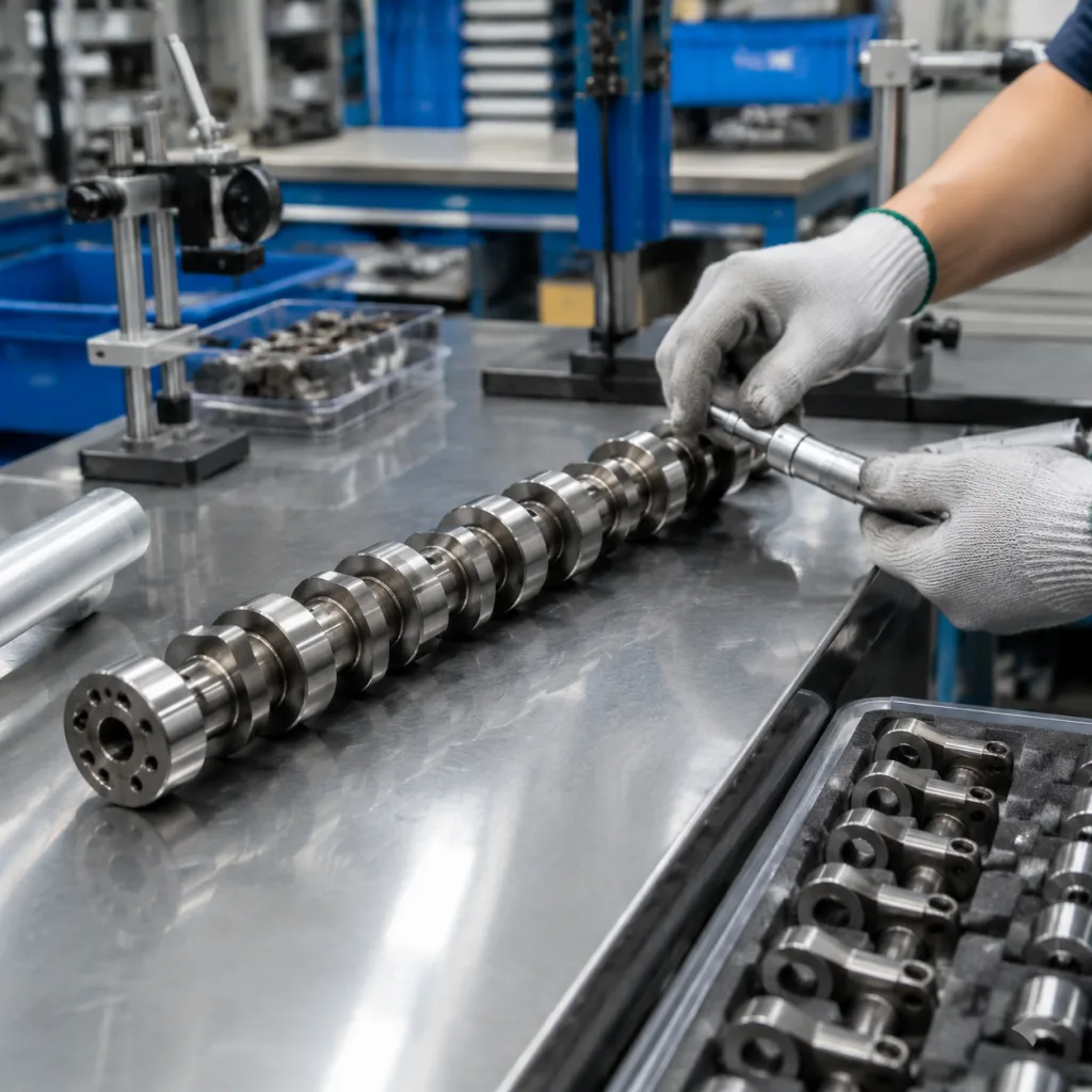
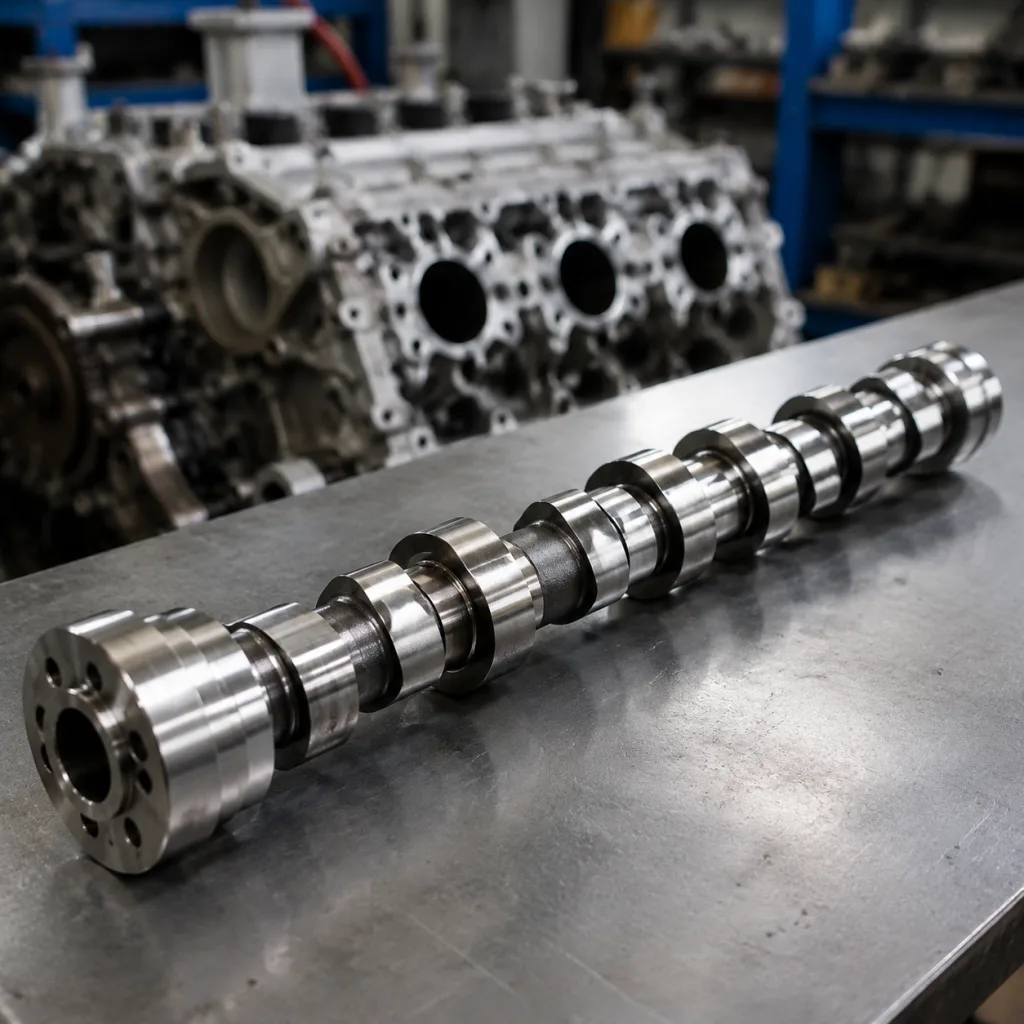
Choosing a camshaft for Ford Escape aftermarket replacement is less about matching a catalog photo and more about matching the engine’s operating behavior. The right part must reproduce the OE lift profile, journal diameter, surface finish, timing reference geometry, and metallurgy within controlled limits. That matters across Escape engine families used in North America, Europe, and export markets. Driventus is an independent aftermarket manufacturer; brand names are referenced for fitment only. We supply engine components for B2B buyers who need repeatable specifications, traceability, and dependable supply. Our camshafts are produced under IATF 16949:2016 and ISO 9001:2015 systems, with material and finish controls aligned to replacement-part expectations. This article focuses on how to decide whether a part is truly interchangeable, where replacement programs fail, and what to request before you place an order.
Is it really interchangeable? Start with the decision points
For a Ford Escape application, the first sourcing decision is not price. It is whether the part is truly interchangeable at the engine level. A camshaft can look correct and still fail if the lobe profile, phasing, or sensor window does not match the OE design.
Check these points first:
- Engine code and production range, not just model year.
- Intake or exhaust position, because the two are often not identical.
- Naturally aspirated or turbocharged variant, since timing and trigger geometry can change.
- OE reference number, sample part, or drawing to confirm the intended application.
- Sensor or sprocket features, which can differ even when the shaft body looks the same.
If those basics are not aligned, the order should stop there. A replacement program works only when the engine family, position, and timing references are locked down before commercial terms are discussed.
Where aftermarket replacements usually fail
Most sourcing problems come from parts that are dimensionally close but functionally wrong. The common failure modes are predictable:
1. Wrong timing reference: the trigger wheel, keyway, or slot is in the wrong angular position, so the engine runs poorly or not at all. 2. Incorrect lobe geometry: base circle or lift is off enough to alter valve event timing, noise, or wear patterns. 3. Poor surface finish: journals or lobes are too rough, which raises scuffing risk and shortens service life. 4. Weak hardness control: the part may machine well but wear early under real oiling conditions. 5. Mixed identification: intake, exhaust, bank, or engine-family labels are unclear, which creates warehouse and installation errors.
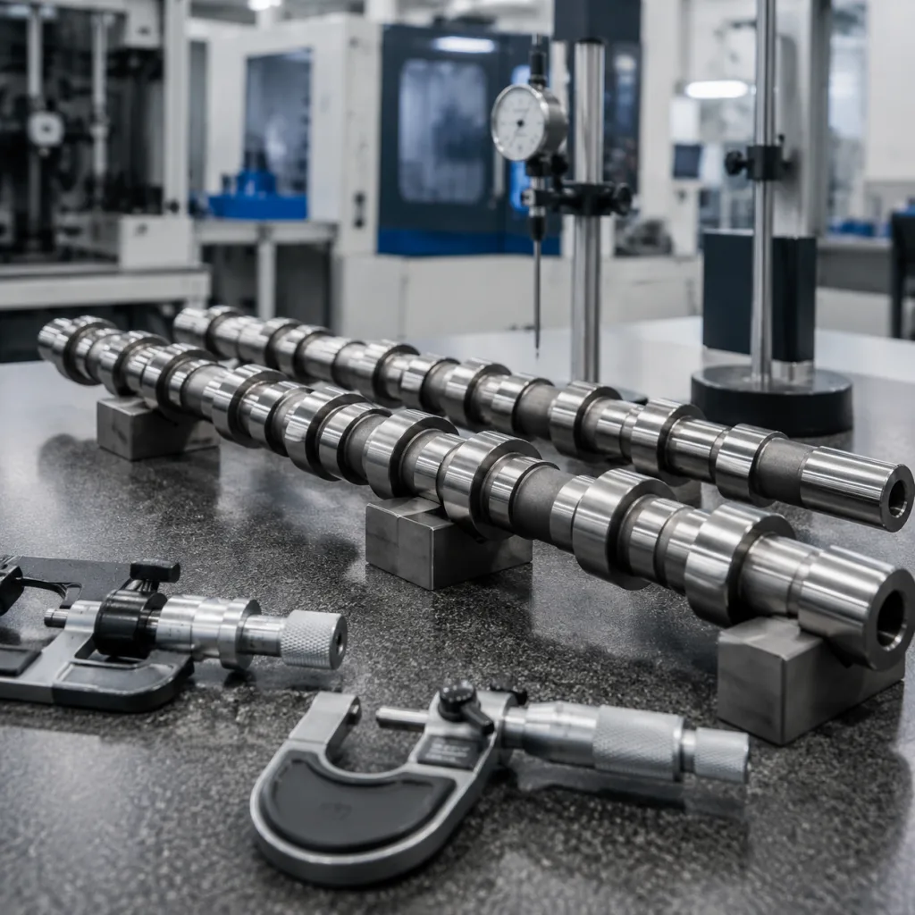
These are not theoretical issues. A shaft with the right overall length can still fail if runout, index angle, or lobe finish is outside the engine’s control range. That is why buyers should treat the inspection report as part of the product, not an optional attachment.
Spec checklist buyers should demand from suppliers
Procurement teams should ask for a controlled specification pack, not a sales sheet. The report should show measured values, not only nominal descriptions.
| Item | What to confirm |
|---|---|
| Journal diameter | Measured to drawing, with actual readings by journal |
| Overall length | Verified against OE sample or print |
| Lobe lift | Recorded by lobe position, with intake/exhaust identification |
| Base circle | Listed for each lobe group to confirm valve event geometry |
| Runout | Measured on V-blocks or between centers |
| Surface hardness | Reported by lot, with test method stated |
| Surface roughness | Ra value for journals and lobes |
| Timing features | Keyway, slot, or trigger wheel position from datum points |
| Material | Alloy steel or cast blank, with heat number or batch code |
| Thrust interface | Verified where axial location control is used |