Cylinder head dimensions determine sealing, valve-train geometry, combustion volume, coolant flow, oil circulation, and block compatibility. For distributors, Tier-1 buyers, and repair-chain procurement teams, the spec has to be precise enough for incoming inspection and stable enough for repeat orders. A head can look correct and still trigger warranty risk if deck flatness, cam bore alignment, valve seat position, coolant passage location, or bolt-hole geometry drifts after casting and machining. This guide focuses on what B2B buyers need to lock down when sourcing aluminium and cast-iron cylinder heads for passenger cars, light commercial vehicles, and selected industrial engines. It covers measurement points, practical tolerance ranges, MOQ and pricing logic, production controls, validation evidence, and documentation expectations. Driventus is an independent aftermarket manufacturer; brand names are referenced for fitment identification only.
Which dimensions actually control fit and function?
A cylinder head drawing should split envelope size from functional size. Envelope dimensions tell you whether the part fits the packaging, machining stock, and installation space. Functional dimensions decide whether it seals, aligns, and survives in service.
For procurement, define the part in numbers, not only in application language. The RFQ should state head length, width, height, gasket-face thickness, chamber volume, valve count, cam configuration, and whether the head is bare, semi-finished, or assembled. For a typical passenger-car aluminium head, overall length often sits in the 350–520 mm range, width in the 130–210 mm range, and height in the 110–180 mm range, but the acceptable value is engine-specific and must tie back to the approved drawing.
A practical spec sheet should cover:
Dimension group
Common measurement points
Typical control target
Procurement relevance
Overall length, width, height
Casting datum to outer faces
Per approved drawing, often ±0.5–1.0 mm on envelope features
Confirms packaging, machining stock, and fitment envelope
Deck face flatness
Full gasket surface
Commonly 0.03–0.08 mm across the sealing surface
Controls head gasket sealing and clamp load distribution
Deck face thickness
Deck to cam cover rail or datum plane
Often ±0.10–0.25 mm on finished heads
Affects compression ratio and allowable resurfacing
Combustion chamber volume
Chamber after final machining
Usually controlled within ±0.5–1.5 cc depending on engine family
Influences compression ratio, knock margin, and emissions performance
Valve guide bore
Bore diameter, depth, concentricity
Micron-level clearance to valve stem, typically 0.010–0.040 mm running clearance
Controls valve stem clearance, heat transfer, and oil consumption risk
Valve seat geometry
Seat angle, runout, depth
Seat angle commonly 45° with 30°/60° top/bottom cuts where specified; runout often ≤0.03 mm
Affects sealing, heat transfer, and airflow repeatability
Camshaft bore alignment
Bore diameter and centreline position
Bore-to-bore variation often ≤0.02–0.05 mm on assembled bearing line
Critical for overhead cam lubrication, rotation torque, and bearing life
Bolt-hole position
Diameter, pitch, and datum location
Positional tolerance commonly 0.10–0.30 mm depending on size and fastener class
Prevents assembly stress and clamp load imbalance
Coolant and oil passages
Port location and shape
Controlled by profile, diameter, and gasket overlay inspection
Supports gasket compatibility, lubrication, and fluid circulation
</tr></thead><tbody> </tbody></table>For replacement programmes, OE part-number cross-references are normally handled through application data rather than by publishing brand-owned numbers. Where a buyer provides a reference such as OE 06A107065 or OE 11251…, Driventus uses it only for fitment interpretation and dimensional comparison, not as a claim of manufacturer approval.
Where tolerances fail in real sourcing programs
Tolerance problems usually show up at the interfaces, not in the headline dimensions. A part may pass a visual check and still fail because the deck is slightly warped, a seat is off-axis, or the cam line drifts after heat treatment. That is why dimensional control has to match the supply condition.
A bare casting, semi-finished head, fully machined bare head, and assembled head should not share the same control plan. The ranges below are typical for quotation and feasibility review; the final limits must follow the approved drawing, sample report, and serial control plan.
Deck face flatness: commonly controlled within 0.03–0.08 mm across the sealing surface, depending on head length, alloy stability, and gasket type.
Surface roughness on deck face: specified by Ra, Rz, or related parameters to match multi-layer steel or composite gasket requirements; common targets range from Ra 0.8–1.6 μm for MLS applications.
Valve guide inner diameter: controlled in the micron range after reaming or honing; target clearance depends on valve stem material, coating, lubrication, and operating temperature.
Valve seat runout: checked with dial, vacuum, optical, or air-gauge equipment to confirm concentricity to the guide and repeatable sealing; many programmes require ≤0.03 mm total indicator reading.
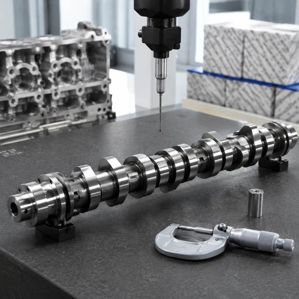
Cam bore diameter and alignment: measured at multiple clock positions and along the bore line to confirm size, roundness, straightness, and oil-film reliability; a common acceptance window is 0.01–0.03 mm per bore with line-bore alignment controlled by the drawing.
Bolt-hole position: verified against datums using CMM, fixture gauges, thread gauges, or a combined inspection method.
Pressure integrity: coolant and oil galleries are checked by air or water pressure testing according to agreed test pressure, dwell time, and leakage criteria; typical shop-floor checks use 0.2–0.5 MPa air hold or a water-leak equivalent.
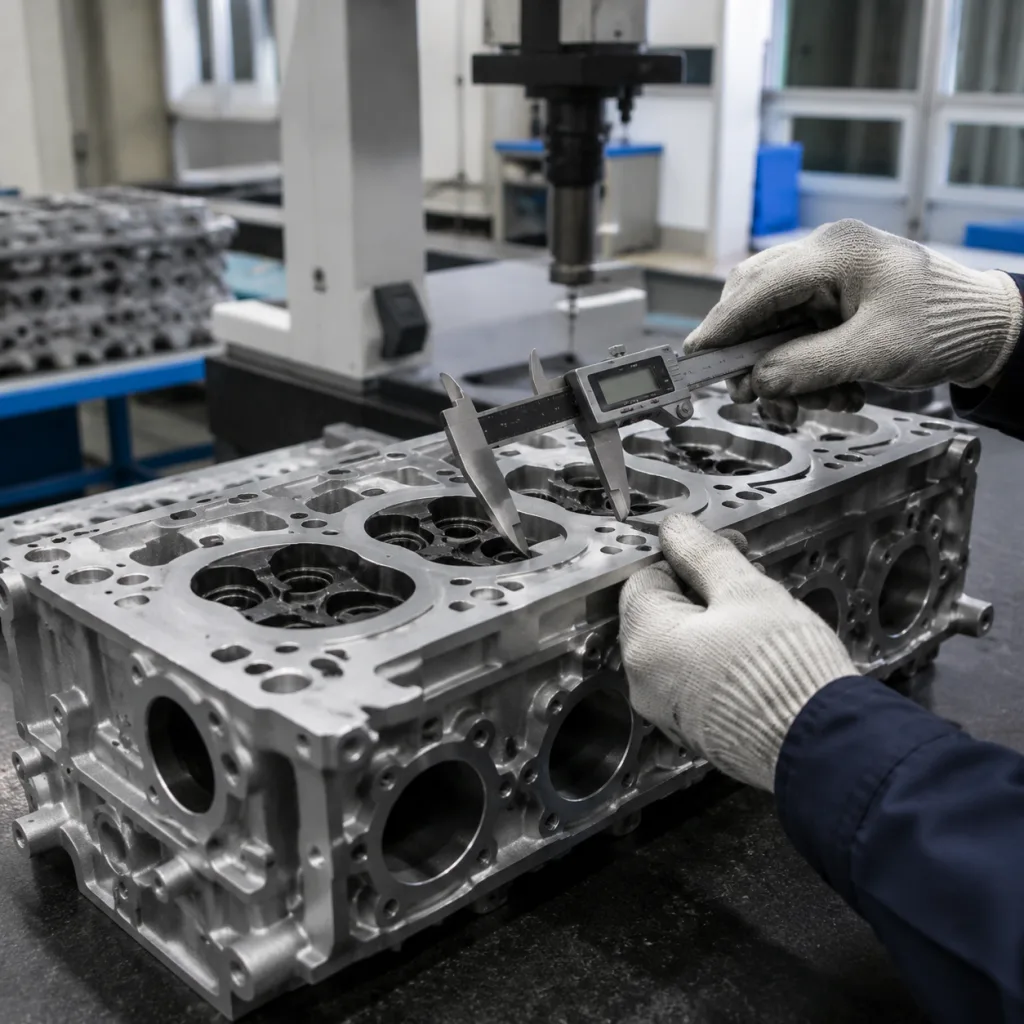
The method matters as much as the number. Deck flatness is usually measured on a granite surface plate with a feeler gauge, indicator bridge, or CMM scan. Chamber volume is measured with a burette or digital volumetric system. Bore size and roundness are checked with air gauges, bore gauges, or bore-mapping equipment. If the drawing does not define the method, the supplier and buyer often argue later even when both measured the same feature.
For serial supply, dimensional inspection should start before final audit: casting checks, machining datum verification, fixture maintenance, tool-wear monitoring, in-process gauging, and first-off approval after tool change. A practical buyer requirement is a first-off report for each new tool setup, plus periodic checks at an agreed sample frequency such as every shift, every batch, or every 200–500 pieces depending on annual volume. Driventus manages these controls within an IATF 16949:2016 and ISO 9001:2015 certified quality system.
Material choice changes the geometry budget
Material is not just a cost decision. It changes machining allowance, distortion risk, thermal behavior, and how much inspection you need before release.
Material route
Typical use
Dimensional considerations
Aluminium gravity casting
Lower-volume or complex head geometries
Requires stable machining datums and controlled porosity
Aluminium low-pressure casting
Higher consistency for water-jacket complexity
Good repeatability, but heat-treatment distortion must be managed
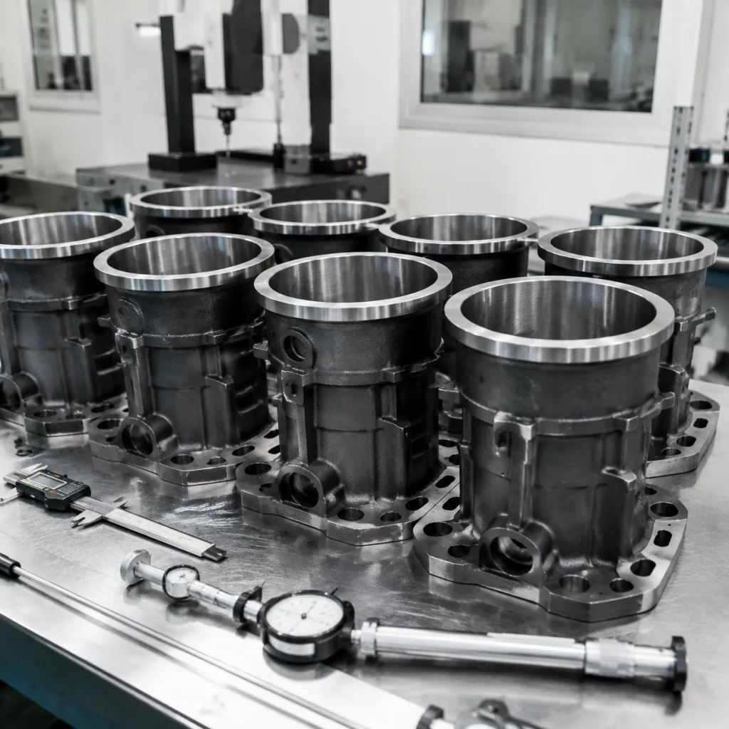
Cast iron
Heavy-duty diesel and industrial engines
Higher mass, stable deck surface, different machining parameters
Fully machined bare head
Aftermarket replacement and engine rebuilding
Buyer must specify guides, seats, plugs, and pressure test status
Assembled head
Repair-chain and distributor programmes
Adds valve train dimensional checks and component traceability
</tr></thead><tbody> </tbody></table>Most modern passenger-vehicle heads use aluminium alloy castings because they reduce weight and improve heat transfer. Cast-iron heads still matter in some diesel, commercial, and industrial applications where strength, thermal fatigue resistance, or legacy fitment wins.
Machining allowance is a sourcing issue, not only a production detail. For aluminium heads, a raw casting may need 2.0–4.5 mm of stock on the deck face and 1.0–3.0 mm on critical port or boss areas before final machining, while cast iron may use different allowances depending on core shift, tool path, and surface-cleanup requirements. Too little allowance exposes casting skin, porosity, core shift, or local hard spots. Too much allowance increases cycle time, tool load, and the risk of dimensional drift as residual stress is released. Heat treatment, quenching, straightening, and ageing also have to match the alloy and casting route so that deck flatness, combustion chamber volume, and cam bore alignment stay stable after machining.
If the head is supplied with valves, springs, seals, plugs, studs, or sensors installed, each subcomponent should appear in the bill of materials and inspection plan. Buyers should also confirm whether the head is supplied bare, with pre-installed valve guides and seats, or fully assembled, because that changes both price and incoming inspection scope. A bare finished head is usually the lowest unit price, while an assembled head adds valve-lash-related checks, subcomponent traceability, and higher defect-cost exposure if the programme is not stable.
Chemical substances, coatings, plugs, thread inserts, impregnation materials, and cleaning agents may also require review under REACH (EC) No 1907/2006 for EU supply chains.
What to put in the RFQ so suppliers can quote fast
A useful RFQ should include more than a vehicle model list. The clearer the dimensional basis, the faster the feasibility feedback and the fewer quotation assumptions. That matters most when one engine family has several similar-looking heads with different port shapes, cam arrangements, sensor positions, or emission-control details.
Recommended RFQ package:
2D drawing with datums, critical-to-quality dimensions, tolerances, thread specifications, and surface finish requirements.
3D model in STEP or another agreed engineering format where available.
Sample part for reverse engineering when drawings are not available.
Target supply condition: casting only, semi-machined, bare finished head, or assembled head.
Application list and fitment notes, including fuel type, displacement, valve count, camshaft arrangement, gasket type, and market variant.
Expected annual volume, order batch size, packaging route, and destination market.
Required documentation such as dimensional report, material certificate, pressure test record, process flow, control plan, and traceability label.
For aftermarket programmes, Driventus can map buyer-supplied references to internal engineering records and application data. Buyers can review related engine components in our catalog or discuss custom manufacturing for drawings, samples, reverse engineering, or private-label requirements. Brand references, where used, remain for fitment identification only.
MOQ and lead time should be requested alongside the drawing, not after the quote. For repeat production, a common MOQ range for a standardized bare head is 50–200 pieces, while a custom programme can require 200–500 pieces or a tooling amortization agreement before the quotation is locked. Lead time is usually 30–45 days for an in-stock or repeat head, 45–75 days for a new machining setup, and 75–120 days when a new casting or tooling change is needed. Ask for price breaks at 50, 100, 300, and 500 pieces so you can compare landed cost rather than just unit price. Specify whether the quote includes pressure testing, corrosion protection, palletizing, and export documentation, because those items can materially change the final commercial result.
How serial approval should be staged
Dimensional approval works better when it is staged. One good sample is not enough evidence that the process will stay stable across batches. Casting, heat treatment, machining, cleaning, assembly, and packing can each introduce variation.
For a new or transferred cylinder head programme, Driventus typically supports:
Engineering review of drawing feasibility, datum strategy, casting route, and machining sequence.
Material verification, including alloy or iron grade confirmation.
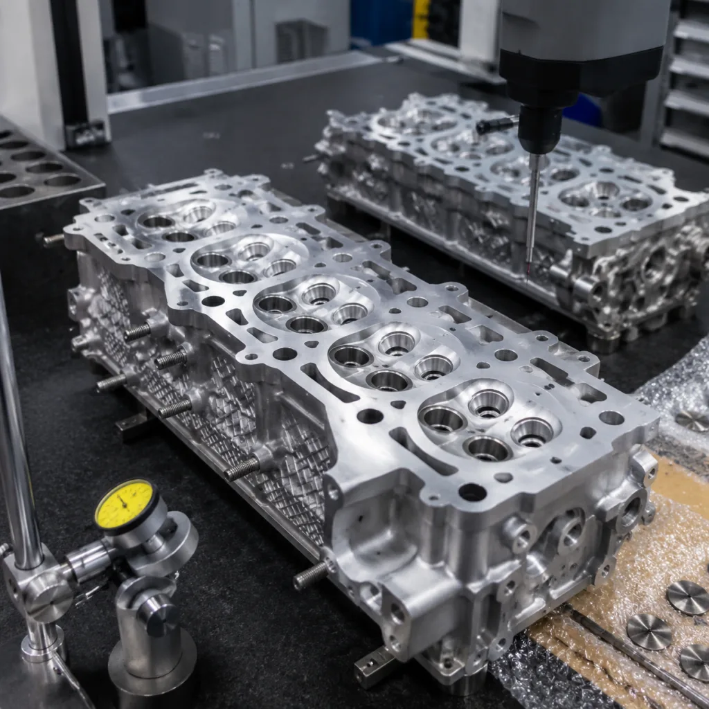
First article inspection with CMM and functional gauge results.
Deck flatness and surface finish reporting after final machining.
Valve guide, valve seat, combustion chamber, and cam bore measurement where applicable.
Coolant and oil gallery pressure testing.
Trial assembly checks using gasket, bolts, valves, camshaft, plugs, covers, and sensors where supplied by the buyer.
Batch traceability from casting lot through final packing.
Ask for a control sample pack on first approval, not only a dimensional report. It should normally include the approved drawing revision, signed first-off report, measurement method, pressure-test record, and packaging approval photos. If the programme is sensitive to failure cost, a short pilot run before production release is worth it, for example 30–100 units with tightened inspection on the first lot and normal sampling after capability is confirmed. That is often the cheapest way to avoid an expensive launch problem.
For markets where emissions durability is part of the buyer’s downstream validation, engine-level testing may need to consider regulatory frameworks such as ECE R-83. The component supplier should not claim vehicle-level compliance from dimensional inspection alone. Cylinder head conformance supports the engine builder’s validation; it does not replace it.
Driventus exports to more than 60 countries and works with distributors, OEM/Tier-1 suppliers, and multi-location repair chains from its manufacturing base in Taizhou, Zhejiang. The commercial file should align engineering approval, packaging, inspection frequency, warranty evidence, service-parts continuity, change-notification rules, MOQ, and lead time before serial orders begin.
What buyers should lock before the PO
Before placing a production order, confirm both the specification and the supply-chain controls. That reduces dispute risk when parts arrive at the warehouse, repair network, or assembly site, and it gives the inspection team one basis for acceptance.
Procurement checklist:
Confirm the approved drawing revision, application scope, and sample approval status.
Define whether inspection follows 100% checks, sampling inspection, or a hybrid control plan.
Specify acceptance limits for deck flatness, surface finish, pressure leakage, combustion chamber volume, and machined bore dimensions.
Confirm whether valve guides, valve seats, core plugs, cam caps, studs, sensors, thread inserts, and other installed components are included.
Require packaging that protects machined faces from corrosion, impact, moisture, and abrasive contamination.
Confirm labelling format, batch traceability, carton quantity, pallet limits, destination compliance needs, and private-label requirements.
Agree on claim handling data: photos, batch code, installation details, measured failure evidence, and return-part review process.
Lock MOQ, target monthly call-off, quoted unit price by volume band, and the latest acceptable ship date.
Set payment terms, Incoterms, and whether the price includes export packing, customs documents, or third-party inspection.
A workable rule is to treat the drawing, inspection plan, and commercial terms as one package. If the dimensional limits are tight but the MOQ is too low for stable production, scrap risk and lead times usually get worse. If the target price is aggressive but the programme includes assembly, pressure testing, and traceability labels, the supplier should confirm what is included line by line before release.
Cylinder head dimensions should be treated as controlled commercial and engineering data. The buyer, supplier, and inspection team should all work from the same revision, datum scheme, measurement method, and acceptance limit. For distributors and repair chains, that discipline also helps keep warehouse substitutions under control when several engine variants look visually similar.
Frequently asked questions
The most critical dimensions are deck face flatness and thickness, bolt-hole position, combustion chamber volume, valve guide and seat geometry, cam bore alignment, and oil/coolant passage location. Their priority depends on the engine design, gasket type, valve-train layout, and whether the head is supplied bare or assembled.
Yes. Driventus can review samples, drawings, and application data for reverse engineering or custom manufacturing. Feasibility depends on casting complexity, machining requirements, expected volume, target documentation, and validation scope. A sample-based project still requires dimensional approval before serial supply.
No. Driventus is an independent aftermarket manufacturer; brand names are referenced for fitment identification only. Documentation can include dimensional reports, material records, pressure test results, traceability data, and quality-system information, but these are not vehicle manufacturer endorsements.
For dimensional review, sample evaluation, or programme quotation, share your drawing, target application, supply condition, MOQ target, and annual volume. You can [request a quote](/contact.html) or contact our engineering sales team at /contact.html