Water Pump Leak Oil Pump Assembly: Diagnosis and Replacement
A water pump leak near an oil pump assembly is usually a coolant-side or front-cover sealing issue, but the visible drip can be misleading. Oil pump housings, timing covers, balance shaft modules, and lower front covers often sit only a few centimetres from coolant passages, so fluid can travel along casting ribs, fastener bosses, gasket joints, and sump rails before the real source shows up. For procurement teams and workshop buyers, the job is to separate a failed water pump mechanical seal from bearing wear, warped mounting faces, compressed gaskets, coolant-side corrosion, casting porosity, or an incorrect replacement part. Driventus is an independent aftermarket manufacturer; brand names and OE numbers are referenced for fitment only. Technical buyers should also check flange flatness, bore alignment, seal-seat finish, pressure-test stability, oil-passage cleanliness, and compatibility with OE 06A107065-style reference patterns where applicable. This article covers the symptom chain, inspection sequence, replacement thresholds, and sourcing checks that help prevent repeat repairs and field returns when dealing with a water pump leak oil pump assembly concern.
What the leak pattern usually means
A visible coolant leak near the front or lower front of the engine does not automatically mean the oil pump assembly has failed. Coolant can come from the water pump weep hole, thermostat housing, coolant flange, bypass hose, front cover gasket, block-to-cover joint, or a casting seam, then run downward or sideways before it drips. Because oil pump housings and lower front covers are often positioned below or beside coolant passages, the final wet area can be 50-150 mm away from the true failure point.
Common symptom sequence
Coolant residue around the lower timing cover, oil pan rail, sump edge, or oil pump mounting flange
Sweet coolant smell after shutdown, especially at the front of the engine after heat soak
Dry upper housing with wet lower casting ribs, bolt heads, or gasket steps
Pink, green, blue, orange, or white crystallised coolant residue on aluminium surfaces
No immediate oil pressure warning, but a measurable coolant loss rate over several drive cycles
Leak volume increasing after highway driving, cooling-system pressure testing, or hot shutdown
The direction of the stain matters. A narrow vertical trail from the water pump weep hole usually points to mechanical seal or bearing failure. A broad wet band along a flange often indicates gasket compression loss, pitted aluminium, sealant contamination, incorrect torque sequence, or reduced clamping load. Coolant collecting at the oil pump mounting line can still originate above the assembly, especially when airflow, belt rotation, pulley spray, and engine tilt move fluid across the front cover.
If the oil pump assembly shares the front cover area, inspect all joint surfaces before replacing parts. A leak that appears at the oil pump mounting line can still come from the water pump seal, thermostat outlet, coolant pipe O-ring, or cover gasket. Symptom location and leak origin are not the same thing. Correct diagnosis starts by cleaning the area, finding the highest fresh wet point, then confirming whether the fluid is coolant, engine oil, assembly lubricant, or cross-contaminated fluid from a failed internal barrier.
Most likely causes on combined front-end assemblies
On engines where the water pump and oil pump assembly are close together, the most common causes are mechanical seal wear, bearing play, gasket failure, casting-surface damage, corrosion, or incorrect installation. The same visible complaint can have different root causes, so technicians should separate coolant-side leakage from oil-pressure or lubrication faults before buyers order a water pump, oil pump assembly, or complete front-end module.
Possible cause
Typical sign
What to check
Water pump mechanical seal failure
Coolant at weep hole, crusted residue behind pulley, bearing noise
Old gasket residue, excess RTV, scratched aluminium, debris under gasket, solvent residue
</tr></thead><tbody> </tbody></table>Water pump mechanical seal failure is often accompanied by shaft noise, bearing roughness, or visible weep-hole discharge. Gasket and housing failures are usually more subtle; they may leak only when the cooling system reaches operating temperature and pressure. Many passenger-vehicle cooling systems are tested around the cap rating, commonly in the 1.0-1.5 bar range, but the exact pressure must follow the vehicle service data. Corrosion-related leakage is common where coolant has been diluted with hard water, mixed with incompatible chemistry, left beyond the service interval, or where dissimilar materials create localised pitting around the sealing land.
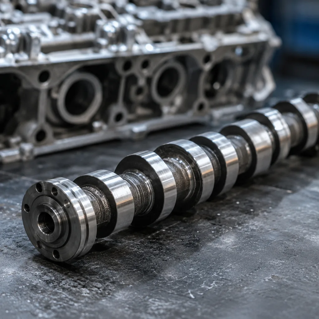
For buyers replacing an oil pump assembly, insist on controlled dimensional verification, not just part-number matching. A correct OE cross-reference, such as OE 06A107065 where relevant, still needs confirmation against engine code, cover design, oil pickup configuration, drive interface, fastener pattern, dowel position, gasket profile, and oil-pressure relief routing. Small differences in housing depth, bypass routing, pickup-tube seat, or bolt-hole position can create sealing stress even when the component appears visually similar.
Inspection steps before ordering replacement
A short diagnostic sequence reduces repeat returns and avoids unnecessary assembly changes. The goal is to confirm the leak source, fluid type, sealing condition, and application data before procurement commits to a water pump, oil pump assembly, front cover gasket set, or complete module.
1. Clean the engine front with non-residue degreaser and dry the area fully with compressed air or a lint-free cloth. 2. Pressure-test the cooling system at the vehicle-specified cap/test pressure, commonly about 1.0-1.5 bar on many light vehicles, and inspect the engine cold. 3. Run the engine to operating temperature, allow a heat-soak period, then recheck with a lamp, mirror, and borescope where access is limited. 4. Check the highest fresh wet point first; gravity, fan airflow, belt movement, and pulley spray can hide the true source. 5. Verify hose clamps, radiator return lines, thermostat housing, bypass pipes, coolant flange O-rings, and water pump weep points. 6. Inspect the oil pump housing face for gasket extrusion, cracks, corrosion, casting porosity, thread damage, and uneven contact marks. 7. Check water pump bearing noise, pulley runout, radial play, and shaft endplay if the pump is driven from the same front module or belt path. 8. Use UV coolant dye, developer spray, or talcum powder tracing when the leak path remains unclear after cleaning. 9. Confirm fluid colour, smell, and texture against coolant, engine oil, assembly lubricant, coolant dye, and residual wash fluid. 10. Record engine code, VIN-derived application data, OE reference, casting number, pickup-tube position, gasket outline, and visible module layout before requesting a quote.
Do not skip surface inspection. A replacement gasket cannot reliably seal a housing face with pitting across the sealing track, raised corrosion, scratches that cross the gasket land, dents around bolt holes, or distortion from previous over-tightening. As a practical workshop check, use a precision straightedge across the flange and compare feeler-gauge readings with the vehicle or component specification. Where no rework specification is published, any visible pitting that crosses the full seal land or any flange damage that prevents uniform gasket compression should be treated as a replacement risk.
If the leak is accompanied by oil contamination in coolant, coolant dilution in oil, sludge under the filler cap, milky residue on the dipstick, foaming in the oil pan, or a sudden oil-pressure change, stop the vehicle. That condition suggests a failed barrier between circuits or broader front-cover sealing damage and requires inspection of the cover, gasket stack, pump housing, pressure relief circuit, pickup screen, and lubrication system before reassembly.
When to replace the full assembly instead of only a seal
A seal-only repair is suitable only when the shaft, bore, bearing support, gasket land, and mating surfaces are within specification and the leak source is confirmed. It is a higher-risk choice when the component has already been removed multiple times, the leak path is uncertain, the housing is corroded, or the vehicle is used in fleet, delivery, taxi, industrial, or other high-duty service where downtime costs more than the part price.
Replace the full assembly when any of the following are present:
Shaft scoring, pulley wobble, bearing roughness, or measurable radial play
Corrosion or cavitation at the seal land, O-ring groove, or coolant passage
Gasket face distortion beyond the service or supplier rework limit
Repeat leakage after a previous gasket, seal, or RTV repair
Coolant or oil contamination inside the housing or adjacent passages
Unclear service history on a high-mileage, overheated, or severe-duty vehicle
A complete assembly is also preferable when the water pump leak oil pump assembly diagnosis points to more than one ageing interface. If the water pump seal is leaking and the adjacent aluminium face is pitted, replacing only one seal may leave the workshop with another seep after refill, bleeding, and pressure testing. Similarly, if the pump shaft has play or pulley runout, a new seal may fail quickly because the rotating surface is no longer stable enough to maintain a controlled seal film.
For procurement teams, the full assembly is often the lower-risk option when labour access is limited. The cost difference between a gasket kit and a complete oil pump assembly can be smaller than the cost of a second removal, coolant refill, oil service, pressure test, road test, and leak verification cycle. For distributors, fleets, and multi-location repair chains, standardising on complete assemblies can reduce fitment variation, installation time, warranty exposure, technician-dependent repair quality, and claim investigation cost.
Driventus production controls for front-end engine pumps
Driventus supplies engine and powertrain components for aftermarket and industrial channels with manufacturing controls aligned to IATF 16949:2016 and ISO 9001:2015. For pump-related parts, the critical controls are machining accuracy, flange flatness, seal-seat consistency, oil-passage cleanliness, controlled assembly handling, and repeatable validation before shipment. These controls matter because a small deviation in bore position, dowel location, flange height, or sealing-surface finish can create leakage or oil-pressure instability even when the part appears visually close to the original.
Our control points include:
CNC-machined housing faces, seal bores, oil-pump cavities, and mounting surfaces
Dimensional inspection of critical diameters, bolt patterns, flange heights, dowel locations, pickup-tube seats, and drive-interface geometry
Surface-finish checks on mechanical seal seats, O-ring grooves, gasket lands, and oil-pump contact faces
Pressure and leak testing where applicable, with recorded test method and acceptance criteria by application
Verification of oil passage cleanliness, deburring quality, relief-valve movement, and casting integrity
Material and batch traceability for castings, seals, gaskets, and machined assemblies
Controlled handling of seal lips, machined faces, threaded holes, and aluminium sealing lands
Export packaging that protects seal lips, dowel holes, threads, gasket faces, and corrosion-sensitive surfaces
For front-end engine pumps and oil pump assemblies, production quality must support both sealing and function. A housing must mount squarely, maintain stable oil delivery, avoid internal bypass leakage, preserve relief-valve operation, and protect the seal stack from contamination. Where the application includes an OE 06A107065-style reference pattern, buyers should still confirm vehicle application, engine code, model year, pickup-tube configuration, and interface geometry before treating the reference as interchangeable.
Published regulatory and customer requirements may also include REACH (EC) No 1907/2006 for material compliance. Application-level validation may include customer-specific endurance, pressure-cycling, thermal-cycling, salt-spray, vibration, or cleanliness requirements rather than a single universal automotive standard. Driventus is an independent aftermarket manufacturer; brand names and OE numbers are referenced for fitment only. See our catalog, review our quality system, or discuss custom manufacturing.
Sourcing notes for distributors and workshop buyers
When you source a replacement oil pump assembly, request the following before purchase:
OE reference, engine code, VIN-range or market-variant confirmation
Vehicle platform, production year range, timing-drive type, and front-cover variant
Seal material specification, such as FKM, HNBR, EPDM, PTFE, or an application-approved equivalent, matched to coolant or oil exposure
Housing material, casting process, heat treatment where applicable, and machining process
Flatness, concentricity, dowel-location, bolt-pattern, cavity-depth, and pickup-seat data where available
Leak-test method, test pressure, duration, and acceptance criteria
Oil passage cleanliness standard, deburring method, and corrosion-preservation process
Included gasket, O-rings, shaft seal, fasteners, pickup tube, relief valve, and installation accessories
Packaging specification for export, including protection for machined faces, threads, and seal lips
Batch traceability, inspection records, warranty handling, and claim-response process
For cross-border supply, the main risk is not only failure in service but also mismatch from incomplete application data. If the vehicle family has multiple front cover variants, confirm timing drive type, pump orientation, coolant passage layout, oil pickup position, sensor ports, relief-valve design, dowel layout, and fastener count. Photos of the removed assembly, casting numbers, VIN-derived engine information, gasket outline, oil pickup image, and connector or sensor positions are useful when catalog data is incomplete.
Distributors should also consider how the part will be installed in the field. Workshops need clear fitment confidence, protected sealing surfaces, consistent accessory contents, and installation notes for gasket placement, sealant restrictions, torque sequence, and pre-lubrication where required. A missing O-ring, wrong gasket profile, contaminated seal face, or damaged seal lip can turn an otherwise correct assembly into a delayed repair or warranty claim. For fleet and repair-chain buyers, it is worth agreeing on packaging, labelling, incoming inspection, and non-conformance criteria before the first volume shipment.
A short technical validation at the sourcing stage usually costs less than one field return. If you need a validated quote for volume supply, request a quote. For broader engine-component sourcing, you can also review our catalog.
Frequently asked questions
Yes. Coolant can run along the front cover, block face, bolt bosses, or sump rail and appear to come from the oil pump assembly. Clean the engine, pressure-test to the vehicle specification, inspect the highest wet point, and check nearby seals, O-rings, and gasket joints first.
Replace only the seal if the shaft, bearing, bore, gasket land, and mating faces are within specification and the leak source is confirmed. If there is wear, corrosion, distortion, contamination, thread damage, pulley wobble, or repeat leakage, the full assembly is the safer procurement choice.
Ask for OE cross-reference, engine-code fitment, material and seal specifications, leak-test criteria, dimensional checks, oil-passage cleanliness controls, included gasket or seal contents, packaging method, and batch traceability. For complex front-end modules, dimensional confirmation is more important than a part number alone.
If you are sourcing a replacement oil pump assembly or need application confirmation for a leaking front-end module, contact Driventus for technical support and a supplier quote: /contact.html