valve spring · 2026-06-04

Valve Spring How to Replace Safely and Verify Fit

People who search for valve spring how to replace often need more than a basic removal sequence. The real question is fit. A replacement spring has to match the exact engine family for free length, installed height, seat load, open load, coil-bind clearance, end geometry, wind direction, material, and heat treatment. It may drop into place and still be wrong if the load curve, installed height, or retainer interface does not suit the valve-train design.

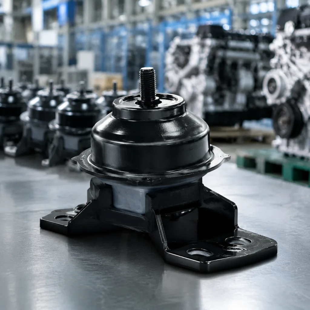
This guide covers how to confirm the application, remove and install the spring safely, inspect the surrounding components, and validate the assembled cylinder head before the engine goes back into service. It is written for workshops, remanufacturers, fleet maintenance teams, and technical procurement teams that need a repeatable process with measurable acceptance criteria. Driventus is an independent aftermarket manufacturer; brand names are referenced for fitment only. If you are sourcing by sample, OE reference, or engine code, keep the old spring, valve-train measurements, vehicle application, and production market together before ordering. That record set is often the quickest way to avoid dimensional drift across model years, regional variants, and earlier repairs.

When replacement is justified

A valve spring should be replaced when it no longer holds the valve closed with the required load, when it cannot control the valve at the engine's operating speed, or when physical damage makes reuse unsafe. Because the spring is fatigue-loaded, visible damage is only part of the decision. Load loss, incorrect installed height, heat exposure, or a mismatched camshaft can create the same service risk even when the part still appears usable.

Common triggers include:

  • Broken coil, cracked end, or missing material at the ground face
  • Visible surface pitting, corrosion, fretting, or scoring from the retainer or seat
  • Reduced free length compared with a known-good sample or the supplier drawing
  • Low seat load or open load on a calibrated spring tester
  • Valve float, high-rpm misfire, unstable idle, or intermittent tappet noise
  • Coil-bind witness marks on the spring, retainer, valve seal, or spring seat
  • Heat discoloration after an overheat event, lubrication failure, or combustion issue
  • Evidence that the spring has been shimmed beyond the engine specification
  • Previous head repair where intake and exhaust springs may have been mixed

Do not assume one failed spring is an isolated part problem. A single broken spring can be traced to fatigue, excess valve lift, incorrect installed height, retainer interference, wrong locator diameter, valve guide wear, or a camshaft and rocker combination that pushes the spring beyond its working range. If the engine has high mileage, unknown repair history, or performance modifications, measure the remaining springs and compare them with the engine specification before deciding whether to replace one position or the full matched set.

For fleet, remanufacturing, and B2B purchasing decisions, replacement is justified when the old spring cannot be proven to meet load and dimensional requirements. Reusing an untested low-cost spring can lead to a much more expensive repeat repair: bent valves, damaged pistons, worn cam followers, or customer downtime. When several springs from the same head show reduced free length or load loss, treat the condition as set-level fatigue rather than a single-location defect.

Tools and measurements to confirm first

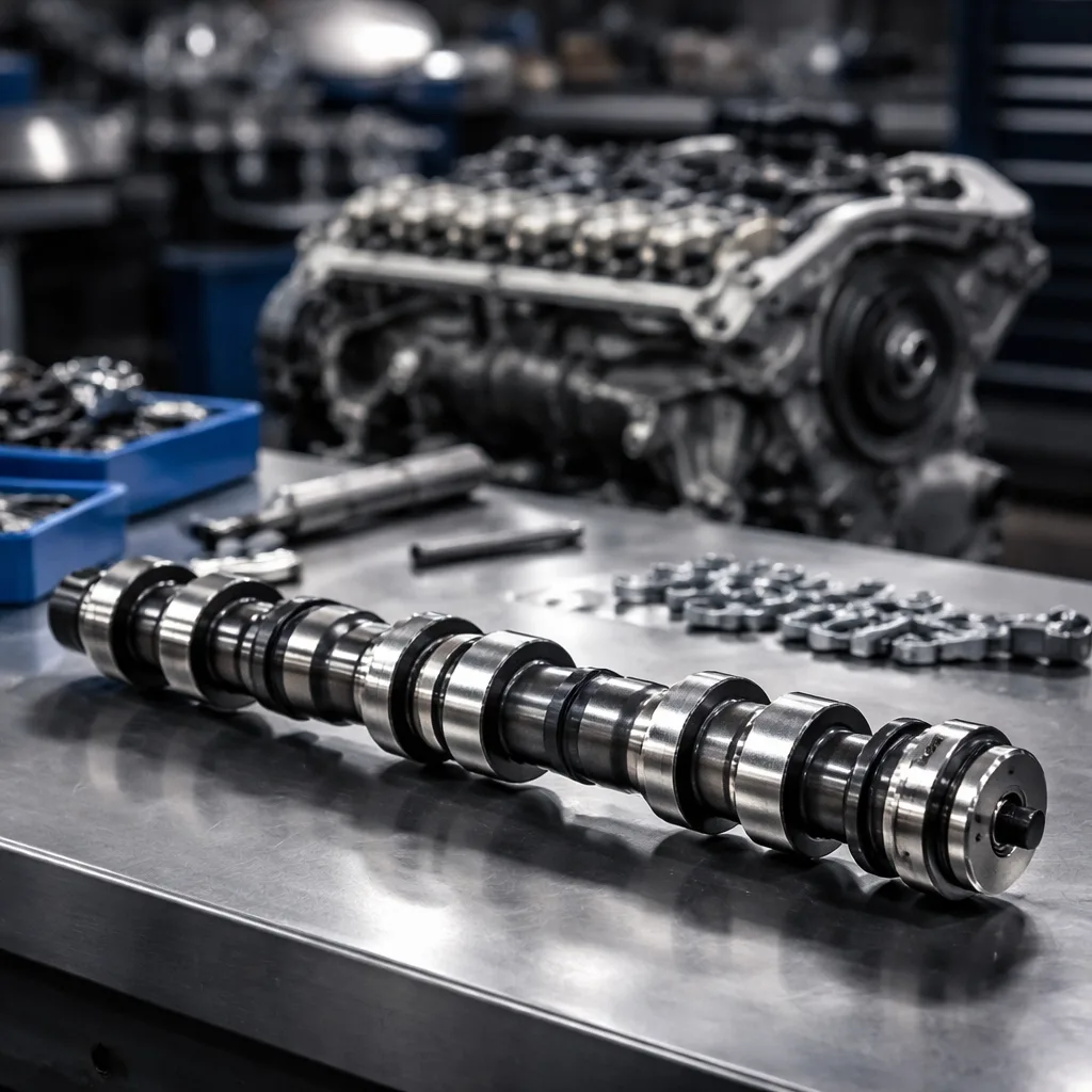
Before disassembly, confirm that the replacement part is compatible with the original application and that the workshop can prove the installed result. At minimum, use a valve spring compressor suited to the cylinder head layout, dial caliper or micrometer, installed-height gauge or depth gauge, spring tester, magnetic pickup or small keeper tool, torque wrench, clean trays for position control, and engine service data for the specific engine code.

If the cylinder head remains on the engine, also prepare compressed air with the correct spark plug adapter or a clean rope method for valve support. If the head is removed, use a bench fixture that holds it stable while the compressor is loaded. For overhead-cam engines, record the cam cap order, timing marks, lash-adjuster positions, and any one-time-use fasteners before removal.

Minimum measurements

</tr></thead><tbody> </tbody></table>Measure the old part, but do not copy wear into the new selection. A fatigued spring may be shorter and weaker than the original design, so evaluate the sample alongside engine data, OE references, and supplier drawings. If the spring sits on a shim, cup, locator, or lower seat, include that complete stack-up in the installed-height calculation. A 0.25 mm change in installed height can meaningfully alter seat load, especially on compact modern valve trains.

For procurement, the useful record set is the part sample, engine code, vehicle application, production year, intake or exhaust position, measured dimensions, load-test values, and supplier drawing revision. For remanufacturing, record the installed height for each valve position before final assembly. That makes it easier to distinguish a spring problem from a machined-seat, valve, retainer, or shim-stack issue later.

Step-by-step replacement procedure

The exact sequence depends on whether the cylinder head is serviced on the engine or on the bench. The control points stay the same: support the valve, compress the spring squarely, keep the keepers under control, inspect the mating parts, and verify installed height before closing the engine. Work one valve at a time unless the head is fully stripped and every component is labeled.

1. Disconnect the battery and clean the work area around the cylinder head or cam cover so debris cannot fall into the oil return, timing area, or valve train. 2. Remove the parts required for access, following the engine manual for ignition components, intake ducting, cam cover, camshaft, rocker arms, lash adjusters, or timing components. 3. If the head stays on the engine, bring the cylinder to top dead center on the compression stroke. Support the valve with compressed air through the spark plug hole or with the rope method so the valve cannot drop into the cylinder. 4. Position the valve spring compressor squarely over the retainer and spring seat. Compress the spring only enough to release keeper tension; side loading can mark the stem, retainer, or guide. 5. Remove the keepers with a magnet or keeper tool, then lift off the retainer and spring. Place parts in a labeled tray by cylinder and valve position. 6. Inspect the valve stem seal, valve tip, keeper groove, retainer, lower seat, shim, locator, and visible guide area before fitting the new part. Replace any damaged related component before continuing. 7. Compare the replacement spring against the original and the specification for free length, outer diameter, inner diameter, wire diameter, end form, coil count, and wind direction if the design is non-symmetrical. 8. Install any lower seat, shim, cup, or locator in the correct orientation. Confirm that the spring sits flat and is centered on the seat or locator. 9. Fit the new spring and retainer, compress the assembly evenly, and install the keepers. Light assembly grease can help hold keepers in place, but excess grease should not contaminate the valve train. 10. Release the compressor slowly while confirming that both keepers seat fully in the valve groove and that the retainer is not cocked. 11. Tap the retainer lightly with a soft tool after release, where the service manual permits, to confirm keeper seating. Do not strike the valve stem directly. 12. Measure installed height on the assembled valve and compare it with the engine specification. Adjust only with approved shims or service parts. 13. Repeat the process for each valve, keeping intake and exhaust springs separated where designs differ. 14. Refit the camshaft, rockers, lash adjusters, timing components, or covers using the service manual torque sequence and lubrication instructions. 15. Rotate the engine by hand through at least two full revolutions. Confirm that no valve binds, no retainer touches the seal or guide, and no spring approaches coil bind at maximum lift.

If the head is removed, the same valve spring how to replace sequence applies, but inspection and measurement are easier and the risk of losing a keeper into the engine is lower. Bench service also allows cleaner checks for valve guide wear, stem seal condition, valve face condition, and seat contact. With a mixed set, label intake and exhaust components immediately; many engines use springs that look similar but differ in load, end form, or installed height.

Inspect the related components

A spring change is only reliable when the rest of the valve train is still within specification. The spring works in a system that includes the valve, guide, seal, retainer, keepers, spring seat, cam profile, follower, lash adjuster, and timing drive. If any of these parts force the spring to run misaligned, over-lifted, overheated, or under-lubricated, the new spring may fail quickly even if it was manufactured correctly.

Check the following parts while the head is open:

Check Target Why it matters
Free lengthMatch sample or drawing within toleranceShortening usually indicates fatigue, heat damage, or permanent set
Installed heightMatch engine specification after seat, shim, and retainer are fittedDirectly changes seat load and valve control
Seat loadPer engine requirement at installed heightKeeps the valve closed at low speed and during compression
Open loadPer cam lift, rocker ratio, and valve-train massResists valve float and bounce at higher rpm
Wire diameterMatch original or validated drawingAffects spring rate, stress, and available travel
Outer and inner diameterMatch seat, locator, retainer, and guide clearancePrevents lateral movement and component interference
Coil-bind clearancePositive margin at maximum valve liftPrevents the spring from becoming solid under lift
End type and wind directionMatch original designAffects seating stability, retainer fit, and paired-spring orientation
Surface finish and treatmentMatch specificationReduces fatigue risk and corrosion sensitivity

</tr></thead><tbody> </tbody></table>If the failure came from valve float, inspect cam timing, lifter condition, rocker ratio, engine speed history, and whether the spring's open load is sufficient for the cam lift. If heat was involved, check cooling performance, oil supply, combustion evidence, and exhaust valve condition. Side wear on the spring points to guide alignment, retainer fit, or seat concentricity issues.

A new spring cannot compensate for a bent valve, worn guide, incorrect retainer, excessive shim stack, or over-lift cam profile. In those cases, replacement should be part of a broader head repair plan. For repeatable repair programs, photograph abnormal wear, record measured clearances, and keep rejected parts until the root cause is agreed. That documentation helps workshops, buyers, and suppliers separate installation issues from material, heat-treatment, or application-selection problems.

Validation and sourcing checks

After assembly, validation should prove both mechanical clearance and operating behavior. Before starting the engine, confirm keeper seating, installed height, retainer-to-seal clearance, spring-to-seat location, and coil-bind margin at maximum lift. Rotate the engine by hand through at least two complete revolutions, and stop immediately if resistance changes unexpectedly. On engines with adjustable lash, set lash to the service specification before start-up; on hydraulic systems, allow lifters or lash adjusters to refill according to the service procedure.

After start-up, confirm that the engine starts cleanly, idles without abnormal valve noise, builds normal oil pressure, and returns to normal behavior under light load. If the design allows it, recheck valve lash after the first heat cycle. For remanufacturing or fleet maintenance, a short validation record should include spring part number, lot number, installed height per position, seat load or calculated-load reference, open-height check, and technician sign-off.

For buyer-side approval, ask the supplier for a dimensional report, material certificate, heat-treatment record, surface treatment or shot-peen record, load-test data at the specified heights, packing specification, and lot traceability. The load report should identify the test height, tolerance, sample size, and inspection date. If corrosion resistance, export compliance, or workshop storage life matters, also request surface protection details and packaging controls.

For controlled sourcing, compare the part family in our catalog, review the quality system, or ask about custom manufacturing when you need a special load curve, material grade, surface treatment, or packaging specification. For broader engine-part programs, see engine components.

Documentation should align with IATF 16949:2016 and ISO 9001:2015 process control expectations. Where corrosion or substance compliance matters, request a REACH (EC) No 1907/2006 declaration. If the supplier cannot show measured load, dimensions, material control, and traceability, a fit claim is not enough. In B2B sourcing, the strongest replacement spring program is not only the part that fits the head; it is the part with repeatable load performance, controlled production records, and clear application boundaries.

Frequently asked questions

Yes, if the failure is isolated and the remaining springs test within specification for free length, installed height, seat load, and open load. In practice, matched sets are safer on high-mileage engines, engines with heat exposure, or any case where fatigue is suspected. If several springs test low, replace the set rather than balancing one new spring against worn parts.

Not always. Many engines can be serviced with the head on the block using the correct valve spring compressor plus compressed air or the rope method to support the valve. Head removal is better when you also need to inspect guides, seals, valves, seats, piston contact, or combustion-related damage.

Ask for dimensions, load data at installed height and open height, material and heat-treatment details, surface treatment, inspection tolerances, packaging details, and lot traceability. A fitment statement without measured data is not sufficient for procurement, remanufacturing, or warranty-sensitive repair programs.

If you need a fitment check, sample comparison, or volume pricing, send the engine code and measurements through our [request a quote](/contact.html).

Request a Quote
Component What to verify Reject if you see
Valve stem sealLip condition, correct height, and firm seat on the guideHardening, tearing, looseness, or oil leakage
Valve guideStem clearance, alignment, and smooth valve movementExcess play, sticking, scoring, or uneven wear
Valve stem and tipStraightness, tip wear, and keeper groove conditionBent stem, mushroomed tip, cracked groove, or scoring
RetainerFlat spring seating, correct diameter, and no cracksGroove wear, deformation, fretting, or poor keeper contact
KeepersFull lock engagement and matched pair contactRounded edges, uneven seating, cracks, or mixed designs
Spring seat / shimFlatness, thickness, location, and correct stack-upBrinelling, galling, missing material, or incorrect shim count
Cam lobe / followerSurface finish, wear pattern, and lubrication conditionPitting, spalling, scuffing, wiped lobe, or abnormal contact
Lash adjuster / rockerFree movement, oil control, and correct ratioCollapse, seizure, excessive play, or incorrect replacement part
Timing systemCorrect timing marks and chain or belt conditionJumped timing, stretched chain, damaged tensioner, or misalignment