Rear crankshaft oil seals are small parts with expensive failure modes. A poor rear main seal material choice can mean oil leakage, clutch contamination, repeat labor claims, and damaged buyer confidence. For aftermarket distributors, repair-chain programs, and OE service channels, the buying spec has to cover more than size. It should lock down the elastomer or PTFE grade, case coating, spring details, lip profile, shaft-finish requirement, inspection evidence, and packaging protection. This guide turns those decisions into practical sourcing controls for petrol, diesel, hybrid, and turbocharged applications. Driventus is an independent aftermarket manufacturer; brand names and OE references are used for fitment identification only.
Decision Point: Match the Material to Heat, Oil, and Shaft Conditions
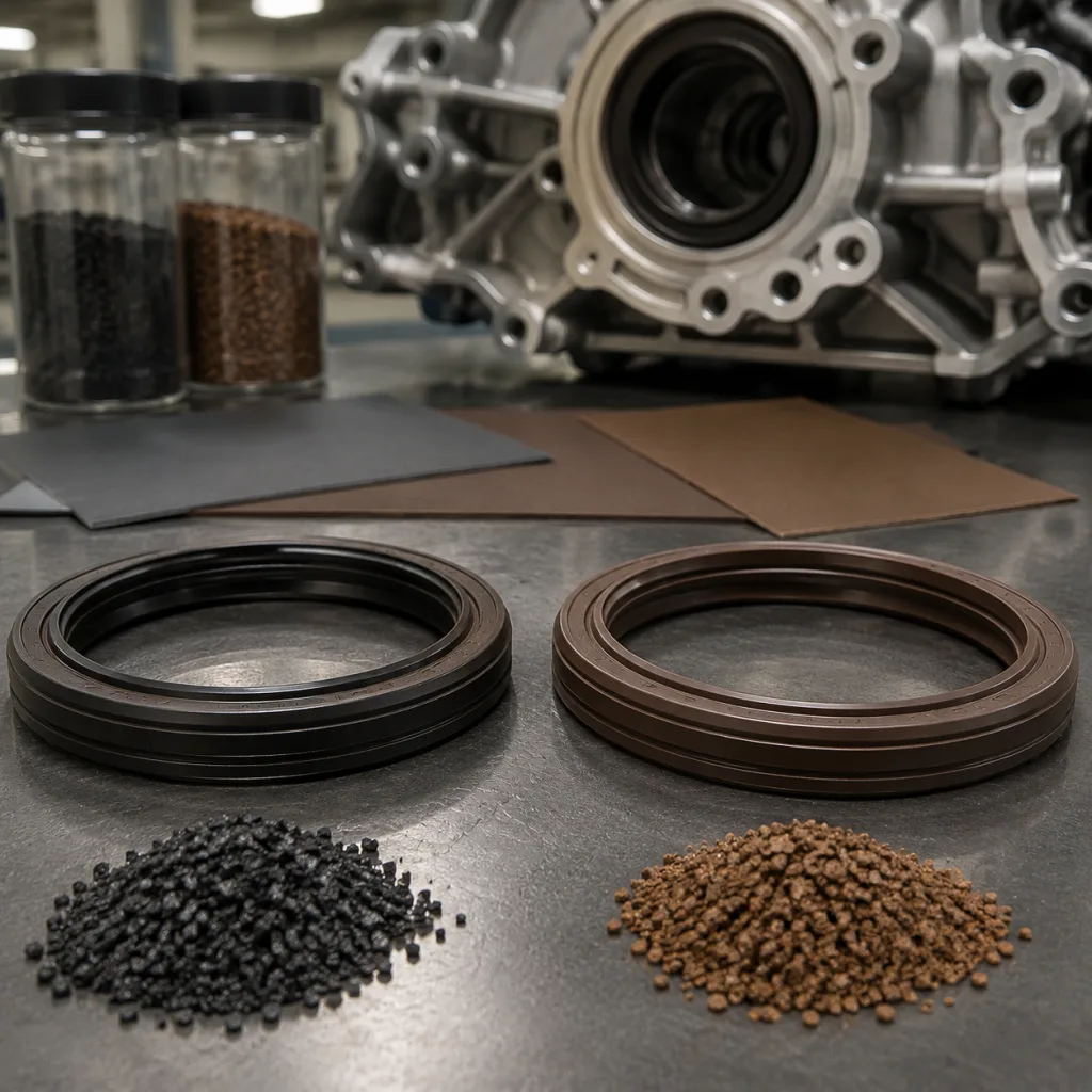
Start with the duty cycle, not the catalogue photo. Rear crankshaft seals usually use either an elastomer sealing lip bonded to a metal case or a PTFE lip assembled into a carrier. The correct rear main seal material depends on oil chemistry, sump temperature, crankcase pressure, shaft finish, duty cycle, installation method, and expected service life.
Specify the material family and compound target. Do not buy by colour, trade name, or interchange alone.
Seal lip material
Typical continuous temperature range
Practical hardness target
Main advantages
Main limitations
Common sourcing use
NBR
-40°C to 120°C
70 ± 5 Shore A
Cost-effective, good resistance to mineral oils, flexible at low temperature
Limited resistance to high-temperature ageing and some synthetic lubricants; verify swelling in modern low-viscosity oils
Older petrol and light-duty diesel applications
ACM
-30°C to 150°C
70 ± 5 Shore A
Better heat and oil resistance than NBR
Weaker low-temperature flexibility than NBR; not ideal for severe cold-start markets
Higher-temperature engine bays and automatic transmission environments
VMQ silicone
-55°C to 180°C
60–75 Shore A
Excellent low-temperature flexibility and heat resistance
Lower tear strength, abrasion resistance, and oil resistance than FKM; needs clean shaft conditions
Cold-climate platforms where shaft condition and contamination are controlled
FKM
-25°C to 200°C
70–80 Shore A
Strong resistance to heat, synthetic oils, fuel vapour, and ageing
Higher cost; requires controlled compounding, cure management, and post-cure evidence
Turbocharged, high-output, and extended-service applications
PTFE
-70°C to 250°C depending on grade and design
Not Shore A-rated; define PTFE grade, filler, thickness, and formed lip profile
Low friction, good chemical resistance, and dry-running tolerance after break-in; often used without a garter spring
Requires precise installation, controlled shaft preparation, and protection from lip damage before assembly
Newer engine programs and low-friction assemblies
</tr></thead><tbody> </tbody></table>For mixed aftermarket coverage, FKM and PTFE become strong candidates when the vehicle parc includes turbocharged engines, long oil-drain intervals, or oil-side temperatures above about 130°C near the rear bearing area. NBR can still be right when the original design used NBR and field temperatures are moderate.
Do not upgrade blindly. Moving from NBR to FKM still needs validation of shaft roughness, lead direction, installation tooling, lip load, and break-in behaviour. Moving from an elastomer lip to PTFE is bigger: treat it as a design change because the lip geometry, running width, shaft finish, and assembly sleeve requirements are different.
Drawing Deep-Dive: The Dimensions That Decide Leakage Risk
A rear seal drawing that lists only inner diameter, outer diameter, and width is not a sourcing specification. Small changes in lip geometry, case interference, or shaft finish can decide whether the seal survives crankshaft runout, thermal growth, and crankcase pressure pulses.
Use the engine drawing where available. If reverse engineering is required, measure multiple original samples because removed seals can be distorted.
Put these controls on the drawing or purchase specification:
Shaft diameter tolerance: control against the engine drawing; supplier inspection should use calibrated plug gauges, air gauges, or approved measuring fixtures. For reverse engineering, record at least 3 positions around the journal and note wear grooves.
Seal outside diameter tolerance: match it to housing bore material, press-fit value, case coating thickness, and retention force. Typical metal-cased OD interference is about 0.10–0.30 mm depending on diameter and housing material; rubber-covered cases may need a different allowance.
Axial width tolerance: critical for cassette-style seals, flange-integrated designs, and housings with limited installation depth. A practical tolerance is often ±0.20 mm for simple seals, while cassette assemblies may need tighter stack-up control.
Primary lip angle and contact width: controlled by mould tooling, trimming, PTFE forming, and final inspection method. Define the inspection section and reject torn, rolled, nicked, or off-centre lips.
Dust lip geometry: required where clutch dust, road contamination, or abrasive particles can reach the seal area. State whether the dust lip contacts the shaft or remains non-contacting.
Garter spring specification: define stainless or carbon spring steel, free diameter, wire diameter, joint type, and spring load where used. For export programs, stainless spring material is often safer where corrosion risk is high.
Shaft surface roughness: elastomer lips commonly need Ra 0.2–0.8 µm and Rz 1–4 µm. PTFE designs often need a smoother, tighter finish such as Ra 0.1–0.4 µm. Follow the engine design requirement where it differs.
Lead-free shaft finish: plunge-ground or polished surfaces are preferred because spiral lead marks can pump oil past the lip. State “no measurable lead” or require supplier confirmation by thread-method or approved lead test.
Installation chamfer and depth stop: protect the lip during assembly and position the contact band on the correct shaft track. Typical chamfer guidance is 15–30° with burr-free edges, but the engine housing drawing takes priority.
Require first-article inspection data for critical dimensions, not just a certificate of conformity. For multi-application aftermarket SKUs, validate cross-references by dimensions, engine code fitment, housing bore, shaft diameter, installation depth, and sealing-interface details. Catalogue interchange is only a starting point.
Failure Mode: Same Material Name, Different Compound Behaviour
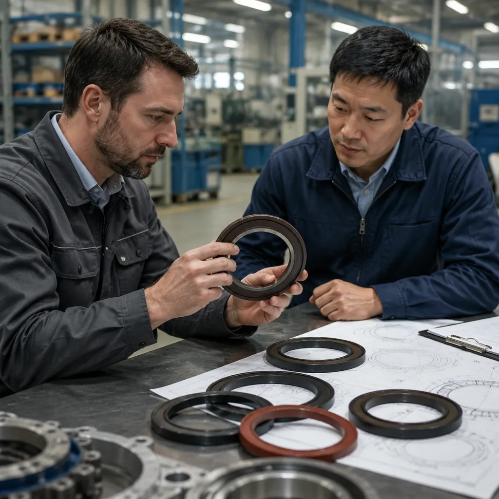
Two suppliers can both quote FKM and still deliver different field performance. Elastomer behaviour depends on formulation, mixing discipline, cure process, post-cure cycle, fillers, plasticisers, and ageing resistance. PTFE also varies by grade, filler system, thickness, forming process, and lip protection.
For rear main seal material approval, request compound-level evidence. A colour match or trade name is not enough.
Key documents and controls to request:
Material data sheet showing elastomer family, hardness target, temperature range, lubricant compatibility, and any PTFE filler system where relevant.
Batch traceability from rubber compound or PTFE billet to moulding lot, assembly lot, inspection record, and finished packed goods. Require lot coding on inner boxes or labels, not only on the master carton.
Hardness test results, normally Shore A for elastomer lips, with tolerance and test condition stated. A common buying tolerance is target ±5 Shore A, with escalation if readings drift more than 3 points between lots.
Heat-ageing comparison before and after oven exposure, with change in hardness, tensile strength, and elongation. Buyers often request 168 h at the material’s rated upper temperature as a baseline screen, with longer exposure for critical programs.
Compression set data where the design depends on static sealing against the housing or carrier. Require test temperature, time, deflection, and acceptance limit.
Oil-immersion data using the specified lubricant or a representative reference oil, including volume change, hardness change, mass change, and visual condition. For elastomer lips, volume change limits of ±5% to ±10% are commonly used depending on compound and oil.
Chemical compliance declaration for REACH (EC) No 1907/2006 where products are placed on EU markets, plus RoHS or PAH statements if the destination customer requires them.
Manufacturing quality controls aligned with IATF 16949:2016 and ISO 9001:2015, including incoming compound checks, cure-time controls, tool maintenance, final sampling, and nonconforming-lot containment.
Driventus applies incoming material checks, in-process dimensional inspection, and outgoing sampling under its documented quality system. For buyer audits, control plans, inspection records, material traceability formats, and retained-sample rules can be reviewed before mass production.
For repeat orders, set a written change-control rule. No compound, spring, case coating, mould cavity, PTFE forming process, or packaging change should proceed without buyer notification and approval.
Validation Sequence: Prove the Seal Before Mass Production
Material approval has to connect to functional testing. A rear crankshaft seal can pass dimensional inspection and still fail after heat ageing, eccentric shaft motion, pressure cycling, poor installation, or exposure to an incompatible lubricant.
Write the test plan before sampling. It should state sample quantity, pre-conditioning, shaft finish, rotation direction, oil grade, speed, temperature, pressure, duration, and leakage limit.
Test item
Purpose
Practical acceptance detail
Dimensional first-article inspection
Confirms housing fit, shaft fit, and drawing compliance
Full dimensional report, usually 5 pcs minimum, against every marked drawing characteristic
Hardness and tensile testing
Confirms compound consistency
Batch test report with target and tolerance; typical hardness tolerance ±5 Shore A for elastomer compounds
Heat ageing
Checks long-term property retention
168 h baseline exposure at rated material temperature; record hardness change, elongation retention, tensile retention, cracks, and surface tack
Oil immersion
Verifies lubricant compatibility
70 h or 168 h in specified oil; record volume change, hardness change, mass change, and visual condition
Dynamic leakage test
Measures sealing under rotation and temperature
Define speed such as 1,500–4,000 rpm, oil temperature such as 120–150°C, duration such as 24–100 h, shaft roughness, and leakage result
Pressure resistance test
Simulates crankcase pressure variation
Cycle positive and negative pressure where relevant, for example -10 to +50 kPa, and define no visible leakage or maximum collected oil
Eccentricity or runout test
Checks lip tracking under shaft movement
State runout value, often 0.10–0.30 mm depending on engine design, plus speed, duration, and leakage observation
Installation trial
Confirms assembly robustness
Use production-intent tool or sleeve; record insertion force, cocking, lip roll-over, spring displacement, and post-install visual inspection
</tr></thead><tbody> </tbody></table>ASTM D2000 and ISO 1629 are often used to classify elastomers, but classification is not the same as approval for a specific engine seal. Production quality management should follow IATF 16949:2016 and ISO 9001:2015 where automotive supply chains require it.
Define the pass/fail limits in the purchase specification. For new tooling or material conversion, approve pilot samples first. Release mass production only after dimensional capability, leakage testing, packaging drop check, and traceability review are complete.
Sourcing Scenario: Catalogue Seal or Custom Rear Main Seal Program?
The fastest answer is not always the safest answer. For distributors, a standard aftermarket seal is usually best when the application is common, the OE-equivalent dimensions are stable, and the original rear main seal material remains suitable. Review our catalog and engine sealing products under engine components when building coverage for high-volume engine families.
Catalogue sourcing usually fits when the buyer can accept the existing material, tooling, packaging format, and validation file.
Custom development is more appropriate when the program needs one or more of the following:
Material conversion from NBR to FKM or PTFE for hotter operating conditions, synthetic oils, turbocharged applications, or longer service intervals.
Private-label packaging with batch traceability, barcode control, market-specific labelling, and carton artwork approval before production.
A cassette seal, integrated flange, wear sleeve, slinger, sensor-compatible carrier, or non-standard metal case design.
Validation to a customer drawing, performance requirement, or internal test plan, including dynamic leakage and installation trials.
A controlled alternative to address recurring leakage, hardening, installation damage, shaft-groove wear, or claim history.
Consolidation of several low-volume SKUs into one managed sourcing project with agreed annual call-off quantities.
Set the commercial frame before sampling. Standard catalogue items can often be quoted from stock or normal production with lower MOQs. Custom compounds, new metal cases, PTFE forming tools, or private-label packaging usually require tooling review and minimum batch quantities.
Aftermarket programs move faster when the buyer shares annual demand, first order quantity, forecast split by SKU, target price range, delivery market, and acceptable lead time. As a planning guide, catalogue replenishment may run 2–6 weeks if components are available. New development commonly requires 8–14 weeks for drawing review, tooling, pilot samples, testing, and packaging approval.
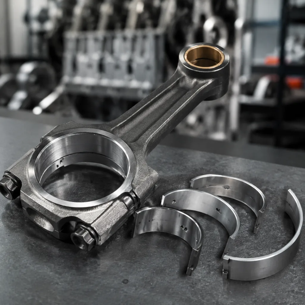
Driventus supports custom manufacturing for rear crankshaft seals, gaskets, pistons, crankshafts, and other engine components. Engineering review should start with the drawing or sample, annual volume, target market, lubricant type, packaging format, and any field failure history. Where no drawing is available, reverse engineering can define dimensions, material family, and housing interface, but final approval should still be based on buyer validation.
RFQ Checklist: Questions That Prevent Costly Assumptions
A strong RFQ reduces sampling loops and prevents false price comparisons. For each SKU or part family, give the supplier the application list, target annual volume, first order quantity, packaging requirement, destination market, and preferred rear main seal material. If there is a target landed cost, state whether it includes tooling, testing, private-label packaging, freight, and spare inspection samples.
Before awarding the order, verify these points:
Seal type: conventional lip seal, cassette seal, PTFE lip seal, wear-sleeve design, or flange-integrated assembly.
Dimensions: shaft diameter, housing bore, width, installation depth, chamfer requirements, and contact band position, with tolerances and datum references.
Material: NBR, ACM, VMQ, FKM, PTFE, or buyer-specified compound, with hardness, oil-immersion, heat-ageing, and compatibility evidence.
Metal case: carbon steel, stainless steel, coating type, corrosion requirement, bonding system, and OD interference allowance.
Spring: with or without garter spring; spring material, free diameter, wire diameter, joint type, and load if specified.
Shaft interface: roughness, lead-free finish, allowable runout, wear-groove condition, and any repair-sleeve requirement.
Test plan: dimensional report, hardness, oil immersion, heat ageing, dynamic leakage, pressure cycling, runout test, and installation check.
Compliance: REACH (EC) No 1907/2006 declaration for EU supply and quality documentation aligned with IATF 16949:2016 and ISO 9001:2015.
Packaging: lip protection, sleeve or insert for PTFE designs, moisture control where needed, part-number labelling, carton strength, pallet method, and private-label artwork approval.
Cross-reference control: use OE-style references only for identification, such as OE 06A… or OE 11251…, and confirm by dimensions, fitment data, and engine code.
Commercial terms: MOQ by SKU, MOQ by material batch, sample cost, tooling cost, payment term, inspection level, warranty handling, and lead time for samples and repeat orders.
The lowest unit price is rarely the lowest landed cost when the seal is underspecified. Compare the full requirement: compound evidence, tooling condition, testing scope, packaging protection, inspection frequency, lead time, claim-handling process, and warranty exposure. A lower quote may simply remove FKM post-cure, reduce PTFE lip protection, change the spring grade, or skip dynamic leakage testing. Those savings can disappear after one leakage claim.
Frequently asked questions
FKM or PTFE is usually selected for higher-temperature engines, turbocharged platforms, or extended oil-change intervals. As a practical screen, specify FKM when continuous oil-side temperatures may exceed about 130°C and PTFE where low friction, chemical resistance, and the original shaft finish support it. The final choice should consider oil type, shaft finish, crankcase pressure, installation method, and original seal design. Changing from an elastomer lip to PTFE requires additional installation controls.
Not always. NBR, ACM, VMQ, FKM, and PTFE have different lip load, friction, ageing, swelling, and installation behaviour. A material change should be validated with dimensional checks, hardness tolerance, oil immersion, heat ageing, dynamic leakage testing, runout testing, and installation trials before release. Elastomer-to-PTFE conversion should be treated as a design change, not a simple material substitution.
Request a drawing or confirmed dimensions, material data sheet, batch traceability method, first-article inspection report, test plan, REACH declaration where applicable, and quality certificates such as IATF 16949:2016 and ISO 9001:2015. Also confirm MOQ, sample lead time, production lead time, packaging, labelling, barcode format, lip-protection method, and whether any compound or tooling change requires written approval before production.
If you are comparing materials for a rear crankshaft seal program, Driventus can review drawings, samples, annual demand, MOQ targets, validation needs, and packaging requirements before quoting. Send the application list and specification to [request a quote](/contact.html).