Piston pin specifications define how a gudgeon pin fits the piston boss, connecting rod small end, and lubrication system. For procurement teams, the critical checks go beyond diameter and length to include wall thickness, bore finish, hardness, roundness, and surface treatment. A pin can still fail in service if its tolerance band, case depth, or coating do not match the engine duty cycle, even when the nominal size is correct. Driventus is an independent aftermarket manufacturer; brand names are referenced for fitment only. We manufacture engine and powertrain components in Taizhou, Zhejiang, and supply B2B buyers in the EU, UK, US, Canada, Australia, and Brazil. Our production and control systems are aligned with IATF 16949:2016 and ISO 9001:2015. This article outlines the main specifications buyers should verify, the standards that commonly apply, and the evidence to request before placing a production order.
Start with the fit decision
The first question is not “what size is it?” It is “what fit does the engine need?” Piston pin specifications only make sense when they are tied to the piston boss, connecting-rod small end, and retention method.
Use this quick decision frame:
Floating pin: choose when both interfaces must move with controlled clearance
Press-fit pin: choose when the rod end must lock to the pin with interference
Semi-floating pin: choose when one side is fixed and the other side moves
Retained pin: confirm whether clips, plugs, or end constraints change the usable length
Once the fit style is known, check the drawing revision, OE cross-reference, and actual measured dimensions together. An OE code such as OE 06A107065 is a fitment clue, not a complete specification. For catalogue review, see our catalog.
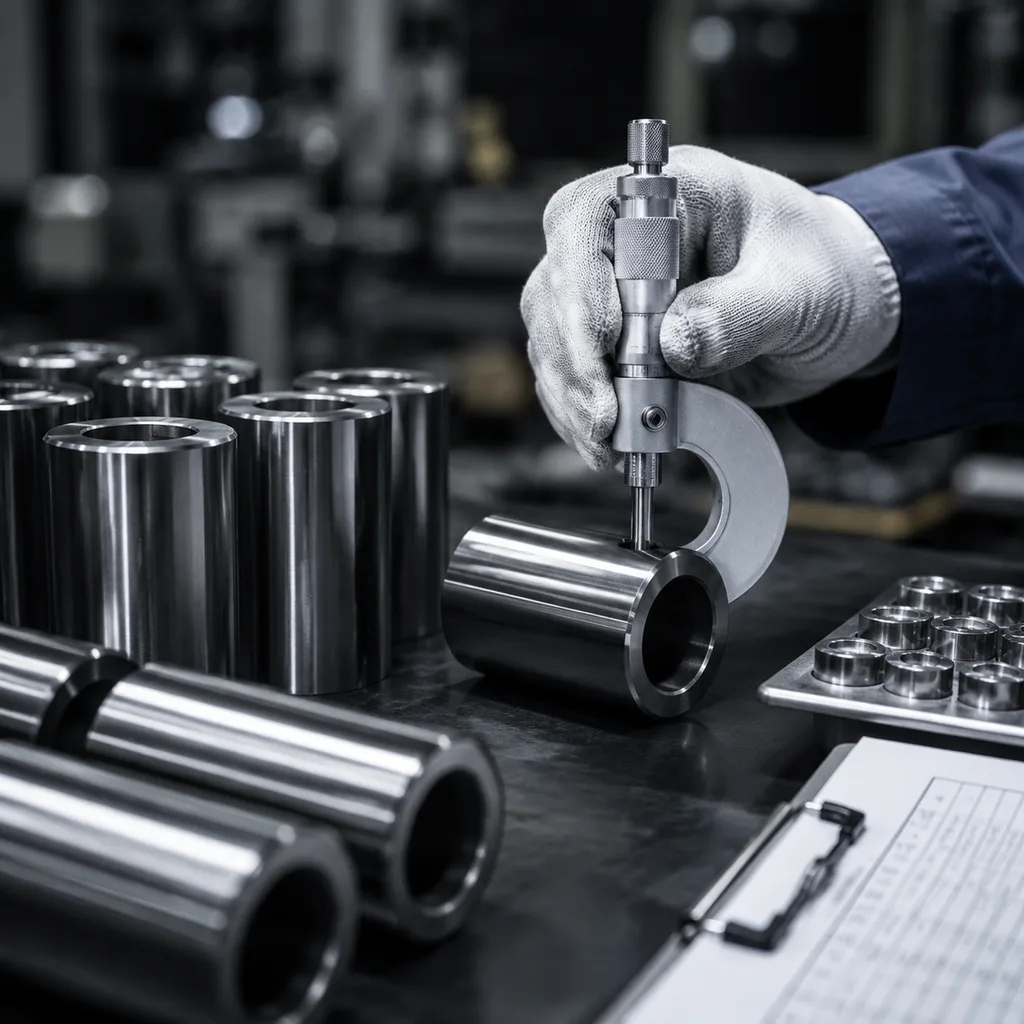
Dimension checks that prevent mismatches
Dimensional control is where most sourcing errors start. A pin can look correct in a sample photo and still miss the application by microns.
Item
Typical control target
Practical tolerance note
Outside diameter
15.000 mm, 19.000 mm, 22.000 mm, or application-specific
Common production tolerance is ±0.002 to ±0.005 mm depending on fit style
Overall length
40 to 80 mm for many passenger-car pins
Hold to ±0.05 mm unless the rod or retainer design is tighter
Wall thickness
2.0 to 5.0 mm on hollow designs
Variation should stay within ±0.10 mm to preserve stiffness and weight balance
Roundness / cylindricity
Form control across full running length
Common buyer limit is ≤0.002 mm for precision-fit applications
Concentricity
Bore-to-OD alignment
Keep within 0.01 mm for floating pins and tighter where the OE drawing calls for it
Surface finish
Ra 0.10 to 0.20 µm on the running surface
A rougher finish increases scuff risk during break-in
</tr></thead><tbody> </tbody></table>If the application uses a hollow design, ask for bore size, wall consistency, and straightness as separate data points. If it uses a solid design, put more weight on OD stability and surface integrity. For drawing-based sourcing support, see custom manufacturing.
Materials and heat treatment choices
Material selection drives load capacity, fatigue life, and wear resistance. Alloy steel is the most common base material for passenger-car and light commercial pins because it balances strength, machinability, and cost. Carbon steel may suit lower-load cases, while higher-duty applications often need a tighter alloy specification and surface hardening.
What to verify:
Base material chemistry and mechanical properties
Surface hardness and core hardness, if both are specified
Heat-treatment route: through-hardening, carburising, or induction hardening
Microstructure for decarburisation, quench cracks, and abnormal grain growth
Residual stress control, especially on thin-wall hollow pins
Typical targets are 58 to 64 HRC at the wear surface for through-hardened or case-hardened designs, with core hardness often around 32 to 45 HRC to preserve toughness. Case depth is usually function-driven rather than generic, but many programmes call for an effective hard layer of 0.4 to 1.0 mm. Ask for batch-level hardness results and the heat-treatment record, not just a one-off sample report.
Where fit classes go wrong
The same nominal diameter can fail in three different ways. Too loose, and the pin scuffs or rattles. Too tight, and assembly force rises or the coating is damaged. Too inconsistent, and one lot fits while the next does not.
Watch for these failure modes:
Floating pins with clearance that is correct on paper but too rough on the running surface
Press-fit pins with interference that changes after coating or heat treatment
Semi-floating designs where one side is stable and the other side drifts out of spec
Endplay errors caused by ignoring clips, plugs, or retainer stack-up
Practical tolerance points to request on a drawing or purchase order:
Pin OD tolerance: often ±0.002 mm for precision floating pins, up to ±0.005 mm for standard replacement parts
Bore size tolerance if the pin is hollow: commonly ±0.01 mm to ±0.02 mm depending on wall thickness and machining method
Length tolerance: generally ±0.03 mm to ±0.05 mm
Straightness: often within 0.01 mm over full length
Surface roughness: Ra 0.10 to 0.20 µm for running surfaces
Coating thickness: typically ±2 to ±5 µm, with OD compensation defined on the drawing
For repeat orders, insist on the same revision level, not only the same part number. That is the simplest way to avoid fit drift between production lots.
Finish, coating, and wear control
Surface finish changes how the pin behaves the moment the engine fires. Ra matters, but it is not enough on its own. The specification should also define post-heat-treatment finish, coating build, and how the finished OD is measured.
Common options include:
Ground and polished steel surfaces for standard service
Phosphate or anti-scuff treatments for break-in support
DLC or other low-friction coatings for demanding duty cycles
Shot-peening on selected designs for added fatigue resistance
A frequent sourcing mistake is approving a coated sample that measures within OD tolerance before coating, then receiving finished parts that run too tight after the coating is added. Avoid that by stating the final finished OD, the coating allowance, and the post-coating inspection method in the PO.
For durability programmes, a practical validation plan often includes 100% visual inspection, sample roughness checks on each lot, and endurance testing for seizure, wear, and coating adhesion. Buyers working on emissions-sensitive programmes should reference ECE R-83 where engine stability matters, and SAE J2527 when the validation plan includes wear or environmental cycling tests.
Evidence to request before release
Procurement teams should ask for proof, not promises. The useful evidence for piston pin specifications is dimensional inspection, hardness data, material traceability, and process control records.
Request these documents:
Material certificate tied to heat or batch number
First article or initial sample inspection report
In-process gauge records for OD, length, and roundness
Hardness report and heat-treatment log
Packaging and corrosion-prevention specification
A buyer-friendly acceptance package usually includes sample approval against the drawing revision, CMM or micrometer records for critical dimensions, Rockwell hardness on at least one part per batch, and lot traceability back to the heat number. For production releases, many sourcing teams also require an AQL-based incoming inspection plan, with tighter sampling on OD and finish than on non-critical features.
Driventus operates under a documented quality system aligned with IATF 16949:2016 and ISO 9001:2015. Where a programme requires a drawing-specific build, the manufacturing route and control plan can be adapted through custom manufacturing. Buyers in regulated markets should also check whether the part chemistry or surface treatment triggers REACH (EC) No 1907/2006 substance review.
Sourcing checklist and RFQ inputs
Before you issue a PO, confirm the data below with the supplier. It reduces dimensional mismatch and avoids delays during incoming inspection.
OE reference and application code
Nominal OD, length, and pin style
Material grade and heat treatment method
Tolerance class for OD, length, and roundness
Surface finish and any coating requirement
Packing method, rust protection, and lot traceability
Required test reports and acceptance criteria
Add commercial detail to the RFQ so the supplier can quote accurately and avoid surprise cost changes. State annual volume, forecast split by month, target launch date, and whether you need sample, pilot, or mass-production pricing. In most pin programmes, MOQ changes with complexity: standard catalogued pins may start at 200 to 500 pieces per part number, while drawing-specific or coated versions often need 1,000 pieces or more to absorb setup and heat-treatment cost. Lead time also varies by maturity: stocked or near-stock items may ship in 7 to 15 days, normal production orders often take 25 to 45 days, and new tooling or special-process parts can take 45 to 60 days or longer.
For price logic, ask the supplier to separate unit price, tooling if any, coating surcharge, and packing cost. That makes it easier to compare quotes on an apples-to-apples basis and to understand when a lower piece price hides a higher total landed cost. If the job is time-sensitive, send the current drawing, target annual volume, and sample or photo of the existing pin. For fast sourcing support, request a quote.
Frequently asked questions
Start with outside diameter, length, fit style, hardness, and surface finish. Those five items determine whether the pin will fit the piston and rod correctly and survive the intended load.
No. An OE reference is useful for fitment, but you should still confirm the actual drawing dimensions, tolerance class, material, and finish. Small revisions can change the part behaviour.
Ask for a material certificate, dimensional inspection report, hardness data, heat-treatment records, and lot traceability. For controlled programmes, add first article approval and packaging requirements.
If you need a drawing-based quote or a cross-reference review, send your part data and target volume through /contact.html.