Low oil pressure does not always start at the pump. In many engine programs, the oil sump is part of the pressure system: it controls oil volume around the pickup, oil movement during load changes, drain-back behavior, sealing integrity, and contamination risk. A 3–5 mm depth error, a distorted baffle, a flange outside gasket compression range, or loose sealant on the pickup screen can turn into aeration, starvation, leakage, and repeat warning-lamp complaints. For distributors, repair chains, fleet maintenance teams, and engine-program buyers, the commercial risk is direct. One poor sump batch can trigger labour claims, pump misdiagnosis, vehicle downtime, urgent stock quarantine, and loss of installer confidence. This guide treats a low oil pressure oil sump complaint as a system problem, then narrows it into evidence: pressure readings, geometry, leakage, cleanliness, fitment, MOQ logic, lead-time planning, and sourcing controls. Driventus is an independent aftermarket manufacturer; brand names are referenced for fitment identification only.
Decision Framework: When the Sump Belongs in the Pressure Diagnosis
Start with a simple question: is the pump receiving a stable, clean oil supply at the correct level? If the answer is uncertain, the sump is part of the low-pressure investigation.
The sump influences four pressure-critical conditions:
Oil available to the pickup: the cavity depth, fill volume, and pickup-screen clearance must match the approved engine application. Many passenger-vehicle programs work around 6–10 mm pickup-to-floor clearance, but the drawing controls. A 4–6 mm dent in a shallow steel pan can restrict inlet flow.
Oil stability around the pickup: baffles, windows, trap doors, ribs, and anti-slosh features keep oil around the strainer during braking, acceleration, cornering, gradients, and off-road use. Visual outer-shape matching is not enough.
Oil retained inside the system: cracks, porosity, drain-plug leakage, sensor-boss leakage, and flange distortion lower the operating oil level between services. A slow 20–50 ml/day loss can become a low-level event before the next oil change.
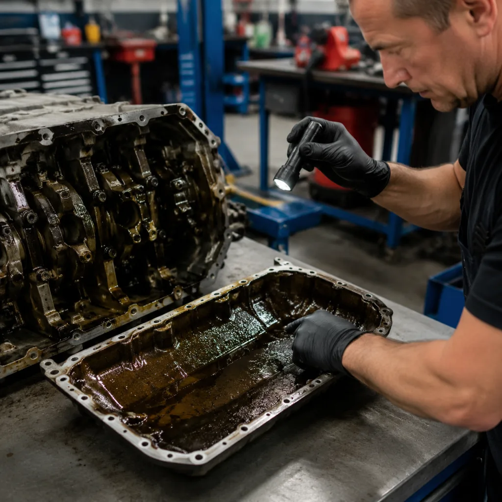
Oil cleanliness entering the pump: RTV strings, gasket fragments, casting sand, welding spatter, coating flakes, swarf, and sludge can restrict the pickup screen. Even 20–30% screen blockage may show up first as a hot-idle pressure complaint.
Useful failure modes are rarely dramatic. A flange that looks acceptable on the bench may leak after heat cycling. A sump with the right bolt pattern may have the wrong internal depth. A repaired drain-plug thread may hold torque once, then seep in service. A baffle may be present but shifted far enough to uncover the pickup during manoeuvres.
Do not replace the pump first by habit. Confirm true low pressure with a calibrated mechanical gauge, then inspect the oil level, filter, lubricant condition, sump, pickup tube, pickup O-ring, and crankcase sealing face as one supply system.
Failure-Mode Map: Symptoms, Evidence, and Replacement Triggers
Use the field symptom to decide what evidence to collect. The table is written for distributor return teams, workshop networks, fleet maintenance, and incoming checks on removed parts.
Field symptom
Likely sump-related failure mode
Evidence to collect
Replace or quarantine when
Oil warning lamp at hot idle
Pickup restriction from sealant, sludge, debris, coating flakes, or sump floor deformation
Mechanical-gauge readings at cold idle, hot idle, and 2,000–3,000 rpm; pickup-screen photos; sump floor profile
The floor is dented into the pickup zone, debris cannot be removed reliably, or measured pickup clearance is outside the approved tolerance
Warning lamp during braking, cornering, or gradients
Missing, loose, cracked, distorted, or incorrectly positioned baffle
Internal photos, baffle comparison against drawing or master sample, weld/rivet check, trap-door movement check
Baffle welds, rivets, hinges, tabs, or anti-slosh features are loose, cracked, missing, or shifted beyond the approved limit
The part does not match the approved application, drawing revision, or master sample; hold the batch until dimensional checks are complete
</tr></thead><tbody> </tbody></table>For service chains, convert this table into a return-authorisation checklist. Require gauge readings, oil level, batch code, installation photos, and sump interior photos before approving labour reimbursement. That one rule prevents many pump, sensor, and lubricant assumptions from becoming paid claims.
Step-by-Step: Prove the Fault Before the Sump Is Replaced
A good inspection sequence protects both sides: the installer avoids unnecessary parts replacement, and the buyer gets evidence strong enough for warranty review.
1. Confirm real low pressure. Record oil grade, fill volume, engine temperature, idle speed, warning-lamp behavior, and readings from a calibrated mechanical gauge. Use the engine maker’s pressure specification where available. If not available, capture cold idle, hot idle, and 2,000–3,000 rpm consistently. 2. Eliminate lubricant and filter causes. Check viscosity, oil age, coolant dilution, fuel dilution, metal particles, and filter bypass condition. Wrong viscosity, fuel dilution above a few percent, or a collapsed filter can imitate a sump-related issue. 3. Check external oil loss. Inspect the drain plug, washer, sump flange, oil-level sensor, sensor boss, crankcase joint, and repaired threads. Confirm plug torque against the service specification. Many passenger-car drain plugs fall in the 25–40 Nm range, but application data is controlling. 4. Review the installation record. Verify gasket type, RTV bead size, curing time, bolt torque, tightening sequence, previous impact damage, and engine-code match. A continuous RTV bead squeezed into the oil cavity should be treated as contamination risk. 5. Remove the sump only when evidence supports it. Before cleaning, photograph the pickup screen, sump floor, baffles, debris pattern, sealant strings, sludge, coating flakes, and impact marks. The debris pattern often explains the pressure behavior. 6. Measure the critical geometry. Compare sump depth, pickup-clearance zone, flange flatness, bolt-hole condition, drain-plug seat, sensor boss, and internal baffle position against the drawing, fixture, or approved master sample. Use a depth gauge or fixture for depth, straightedge and feeler gauge for flange screening, and CMM or dedicated gauges for production approval. 7. Inspect associated parts. Check the pickup tube, pickup O-ring, oil-pump inlet, crankcase sealing face, fasteners, and oil return path before fitting a new sump. A hardened O-ring or distorted pickup tube can mimic a sump defect. 8. Preserve claim evidence. Link photos, debris, pressure readings, and carton labels to the installed batch. Keep the sump unwashed until the supplier confirms what evidence is needed.
For aftermarket supply, Driventus controls production under IATF 16949:2016 and ISO 9001:2015. Incoming materials, stamping or casting dimensions, machining features, coating adhesion, cleanliness, and leak performance are covered in our quality system.
Spec Deep-Dive: What the Purchase Drawing Must Control
Replacement is justified when the sump can no longer maintain oil volume, pickup stability, sealing integrity, or internal cleanliness. For B2B sourcing, those limits belong in the purchase specification. Visual similarity is not enough; two parts can share a bolt pattern while differing in depth, baffle design, drain-plug geometry, or sealing-face control.
Define these points before the first order:
Material and construction: stamped steel, cast aluminium, or engineered polymer according to the OE design and engine environment. Specify steel thickness range, aluminium alloy, polymer grade, heat condition, coating condition, and any equivalent-material rules.
Flange flatness: control the full sealing perimeter and local areas around bolt holes, corners, bosses, and formed transitions. A common buyer limit is 0.30–0.50 mm total indicator reading on stamped steel flanges, with tighter local rules where gasket compression is critical; the gasket design should set the final number.
Critical geometry: define sump depth, pickup-clearance zone, cavity profile, baffle position, oil-return areas, and datum points. Do not rely on overall height alone.
Thread and seat integrity: verify drain-plug and sensor threads with go/no-go gauges where applicable. Include thread cleanliness, burr control, seat finish, washer interface, and torque-test evidence for new tooling or supplier changes.
Leak performance: specify test method, pressure level, hold time, and acceptance criteria. Aluminium or welded sumps are often tested at 20–50 kPa for 10–30 seconds, with zero bubble leakage or a defined pressure-decay limit.
Coating system: set corrosion protection for road salt, storage humidity, and export logistics. Include film thickness, exposed-edge protection, salt-spray target, adhesion method, and masking rules for sealing faces and threads.
Internal cleanliness: prohibit loose shot, casting sand, machining swarf, welding spatter, sealant residue, burrs, and excess coating inside the oil cavity. For high-risk programs, require washing, filtered air blow-off, white-cloth inspection, and maximum particle size or mass per part.
Baffle retention: define weld length, nugget count, rivet security, clip retention, tab formation, pull checks, and fixture verification where the design allows.
Packaging protection: protect the flange, plug thread, sensor boss, drain-plug seat, and coating during container transport and warehouse handling. Use separators, thread caps, corner protection, and carton-compression criteria for export pallets.
Traceability: link production batch, material lot, process route, inspection record, leak-test result, and carton label. A useful minimum is date code, line or shift, material lot, leak-test record, and final inspection result.
Standards help frame the control system. IATF 16949:2016 and ISO 9001:2015 support process control, traceability, corrective action, and quality-system discipline. REACH (EC) No 1907/2006 may be relevant for EU material and coating declarations. ECE R-83 applies to vehicle emissions type approval, not oil sump approval, although oil-control failures can affect emissions durability and catalyst life in service. Driventus does not claim approval or endorsement by any vehicle manufacturer.
Sourcing Scenario: The Bolt Pattern Fits, but the Program Still Fails
Consider a private-label distributor that launches a visually correct sump across several engine codes. The bolt pattern matches. The first shipment sells quickly. Then claims arrive: hot-idle warning lamps, gasket leaks, and one branch reporting low pressure after replacement.
The likely issue is not one single defect. It is usually a sourcing-control gap. The application matrix may have merged similar variants. The internal baffle may not match the master sample. Packaging may be bending flanges in transit. The leak test may not cover welded seams or sensor bosses. Cleanliness may be judged cosmetically, while loose coating flakes remain inside the oil cavity.
Build the sourcing file around evidence, not assumptions:
Fitment separation: confirm application coverage, engine-code compatibility, model-year range, and OE part-number cross-references where provided, such as OE 06A… or OE 11251… formats used only for fitment identification. Separate variants by depth, sensor port, baffle layout, and drain-plug location.
Dimensional proof: review reports for flange profile, bolt holes, plug seat, sensor boss, sump depth, baffle position, and pickup-clearance-related features. For first orders, request a 5-piece layout report per SKU or cavity/tool, then move to AQL or control-plan sampling after stability is proven.
Leak-test discipline: require the method, test pressure, hold time, acceptance criteria, calibration control, and sampling frequency. Cast aluminium or welded assemblies often justify 100% leak testing; simple stamped pans may use sampling if process capability is documented.
Cleanliness control: verify washing, deburring, post-machining inspection, and protection from coating overspray or loose particles. Add a written rule for no loose debris in the oil cavity.
Corrosion and storage planning: define coating specification, salt-spray or corrosion target, film thickness range, and handling rules. If parts sit in humid warehouses for 60–120 days, packaging and anti-rust controls matter as much as coating chemistry.
Transport validation: check packaging through drop, vibration, compression, or transport simulation where export damage is a known risk. A bent flange can create a warranty case even when the production part passed inspection.
PPAP-style evidence: for OEM, Tier-1, fleet, or structured private-label programs, request process flow, control plan, FMEA summary, material report, dimensional report, leak-test evidence, coating report, packaging approval, and sample parts.
Claim accountability: require batch traceability from material lot and production date to carton label. Define who pays for labour, return freight, destructive testing, and replacement stock when a batch-level issue is confirmed.
MOQ, price, and lead time also belong in the control plan. Stocked catalogue oil sumps are often planned by carton or pallet quantity, commonly 100–300 pieces per SKU depending on size and packaging. New-tooling or private-label SKUs are driven by tooling amortisation, coating batch size, packaging print quantity, and container utilisation, so 300–1,000 pieces per SKU is more realistic. Price moves with material, wall thickness, machining, leak-test requirement, coating, drain plug or gasket inclusion, packaging level, and documentation. Lead time is shortest for stocked items, often 2–4 weeks before shipment after order confirmation; repeat production commonly needs 30–45 days; new development with drawing confirmation, sample build, leak validation, packaging approval, and pilot order may require 60–90 days before mass shipment.
Driventus manufactures engine and powertrain components in Taizhou, Zhejiang, and exports to more than 60 countries. Buyers can review oil sumps and related engine parts in our catalog, discuss private-label or drawing-based custom manufacturing, or request a quote for program-level sourcing.
Warranty Q&A: What Evidence Decides the Claim?
What makes a low-pressure claim reviewable?
A claim becomes reviewable when the record separates pressure loss from installation error, lubricant condition, filter failure, engine wear, sensor faults, and shipping damage. At minimum, record vehicle application, engine family, engine code, mileage, service date, repair site, repair order number, installer name or branch, and installed part batch.
Which pressure data matters most?
Use a calibrated mechanical gauge. Capture cold idle, hot idle, and elevated-rpm readings with engine temperature noted. Include the gauge calibration date or tool ID where possible. A warning lamp alone is not enough.
What service details should be included?
Record oil grade, oil level before draining, oil brand where available, filter brand or specification, service interval history, and signs of coolant or fuel dilution. Add gasket or sealant type, sealant bead size, curing time, sump bolt torque, drain-plug torque, tightening sequence, and whether fasteners were reused.
Which photos reduce dispute?
Photograph the sump exterior, flange, drain-plug seat, plug threads, sensor boss, baffles, pickup screen, gasket surface, and debris before cleaning. Use a ruler or scale for dents, flange gaps, baffle displacement, or impact marks. If the issue appears before or shortly after installation, photograph the carton, label, pallet code, and transit damage.
What evidence points away from a product defect?
Incorrect application, excess sealant, reused or wrong washer, over-tightened drain plug, thread damage, impact damage, contaminated oil, collapsed filter, shipping deformation, previous repair work, and pressure loss after a long service interval can all shift the root cause away from the sump manufacturing process.
How should buyers use the data commercially?
Consistent records support clear decisions: approve credit, deny unsupported claims, request 8D corrective action, quarantine remaining stock, revise packaging, adjust MOQ by SKU, tighten incoming inspection, or update the purchase specification. Good field feedback also points to practical fixes such as stronger flange protection, revised baffle inspection, improved washing, or tighter leak-test controls.
Frequently asked questions
Yes. A dent can reduce clearance around the pickup strainer, restrict oil flow, and make the pump draw aerated or insufficient oil, especially at hot idle or during manoeuvres. On many light-vehicle sumps, a 4–6 mm dent in the pickup zone is enough to justify removal and measurement. If impact damage is visible, the sump should be removed, cleaned, and checked against the pickup clearance specification or approved master sample.
No. First confirm pressure with a calibrated mechanical gauge, then inspect oil level, lubricant condition, filter condition, pickup screen, sump geometry, pickup O-ring, and bearing-related symptoms. Replacing the pump without checking the sump can leave the root cause unresolved and may create repeat labour claims.
Buyers should verify application coverage, engine-code fitment, flange flatness, sump depth, baffle position, pickup-clearance-related geometry, leak testing, thread gauges, coating requirements, internal cleanliness, packaging protection, MOQ, lead time, price drivers, and batch traceability under a documented quality system.
If you are reviewing low oil pressure oil sump failures or building a replacement program, Driventus can share application coverage, inspection controls, validation documents, MOQ options, lead-time planning, and export packaging choices. Send your requirements through /contact.html