Harmonic Balancer How to Replace: B2B Fitment Guide
A harmonic balancer reduces torsional vibration at the crankshaft nose and helps maintain correct auxiliary belt alignment. On many engines it also carries the accessory pulley surface, timing mark, or crankshaft trigger feature. When the rubber isolator cracks or separates, the hub frets, the pulley runs out, or the timing reference shifts, symptoms can include belt noise, charging faults, crankshaft sensor errors, front oil seal leaks, and vibration that is easily mistaken for an engine mount or flywheel problem.
This guide explains harmonic balancer how to replace from both workshop and procurement viewpoints. It covers what to inspect before removal, which dimensions to confirm before installation, and which process controls reduce repeat claims across mixed engine platforms. It is written for importers, distributors, repair chains, fleet maintenance teams, and technical buyers who need repeatable replacement standards rather than one-off repair advice.
Driventus supplies harmonic balancers and related engine components from Taizhou, Zhejiang, under IATF 16949:2016 and ISO 9001:2015 controls. Driventus is an independent aftermarket manufacturer; brand names and OE references are used only to support fitment identification.
When Replacement Is Required
A harmonic balancer should be replaced when inspection confirms physical degradation, pulley runout, hub damage, or loss of timing accuracy. It should not be replaced only because an auxiliary belt has failed. Belt wear can also be caused by tensioner misalignment, a seized idler, overrunning alternator pulley failure, contamination, incorrect belt length, or poor previous installation.
Typical replacement triggers include:
Visible cracking, glazing, swelling, hardening, or extrusion of the rubber damping ring
Pulley wobble or measurable runout at the outer ring while the engine is idling
Separation between the hub and inertia ring
A shifted timing mark on engines using an external timing reference
Grooving, corrosion, or wear at the crankshaft oil seal contact area
Keyway damage, fretting marks, or an elongated crank bolt bore
Repeated auxiliary belt tracking faults after tensioner and idler checks
Low-speed vibration after engine mount, flywheel, clutch, and accessory-drive causes are excluded
For multi-location repair chains, a written inspection checklist helps technicians separate true balancer faults from belt-drive faults and reduces unnecessary warranty returns. For distributors, the same checklist gives counter staff a consistent way to handle customer complaints about a failed replacement part.
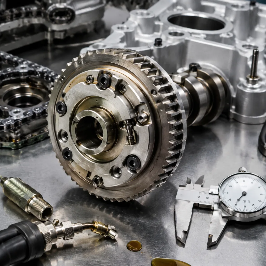
Buyers reviewing our catalog should match the balancer by engine code, production range, pulley rib count, offset, bore geometry, mounting style, and crank trigger or timing features where applicable. Similar engine families can use visually close parts with different offsets or trigger profiles, so application data should always be confirmed against physical dimensions when sourcing in volume.
Tools, Parts, and Pre-Installation Checks
Before removal, confirm whether the engine uses a torque-to-yield crankshaft bolt, a keyed hub, an interference-fit hub, a locating dowel, or an integrated crank trigger pattern. Many crank bolts are designed for single use and must not be reused. Vehicle service data should be followed for the holding method, torque value, torque angle, thread treatment, and locking procedure.
Check item
What to verify
Why it matters
Outer diameter
Match sample, drawing, or catalogue tolerance
Controls belt speed and accessory drive ratio
Pulley ribs
Rib count, groove pitch, and groove profile
Prevents belt walk, noise, and premature belt wear
Offset
Hub face to pulley centreline
Maintains alignment with tensioner, idlers, and accessories
Bore and keyway
Diameter, chamfer, key position, and surface finish
Prevents crank nose fretting and installation damage
Damping ring
Bonding quality, concentricity, and rubber hardness
Controls torsional vibration and service life
Timing feature
Mark, notch, reluctor, or trigger profile
Avoids crank sensor, ignition, and timing errors
Bolt and washer
Correct new fastener where specified
Maintains clamp load and reduces hub movement
Seal surface
Sleeve, hub finish, or wear groove condition
Helps prevent front crankshaft oil leaks
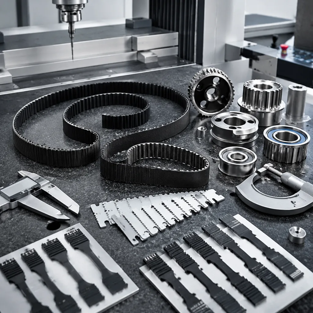
</tr></thead><tbody> </tbody></table>Recommended tools include a crankshaft holding tool, correct puller or installer, calibrated torque wrench, angle gauge, belt alignment gauge, dial indicator, seal inspection light, and non-metallic cleaning tools. Some engines also require a special service tool to protect the front crank seal or to install the balancer to a controlled depth.
Do not lever against the outer ring, and do not pull on the inertia ring unless the service tool is specifically designed for that part. Force applied through the rubber section can tear the bond or distort the pulley before the new balancer is even in service.
Removal Procedure
The exact removal sequence varies by engine family, vehicle layout, and access, but the control points are consistent. Disconnect the battery when working near starter, alternator, or main charging wiring. Remove splash shields, undertrays, cooling fan shrouds, wheel-arch liners, or engine mount brackets only as required for safe access. Record belt routing before the belt is removed.
1. Inspect the belt path before disassembly. Look for misaligned idlers, weak or seized tensioners, coolant or oil contamination, damaged pulley grooves, and abnormal belt dust. 2. Confirm the correct locking method. Lock the crankshaft using the specified holding tool or flywheel tool. Avoid the starter motor bump method, especially on engines with limited access, unknown service history, or torque-to-yield bolts. 3. Loosen the crankshaft bolt according to service data. If the bolt is torque-to-yield or otherwise specified as single-use, discard it after removal. 4. Mark the old balancer orientation only if it helps comparison or diagnosis. Do not rely on paint marks as a substitute for correct timing alignment during installation. 5. Use the correct puller on the hub or specified puller holes. Do not transmit removal force through the rubber ring or outer inertia mass. 6. Inspect the crankshaft nose, key, keyway, washer face, bolt threads, and oil seal running surface once the balancer is removed. 7. Clean corrosion and residue from the crank nose using approved methods. Abrasive cleaning that changes diameter, roundness, or surface finish can reduce clamp load and create runout.
If the old balancer has separated, inspect nearby components for secondary damage. Belt fragments can enter timing covers, crank seals, cooling fan areas, or lower engine shields. A repair chain dealing with repeat failures should retain the removed component, bolt, and belt until the installation cause has been confirmed. That evidence is often more useful than a simple claim note saying the pulley failed.
Installation Procedure and Torque Controls
Compare the replacement part with the removed unit before installation. Confirm the application by dimension, rib count, hub depth, bore style, keyway or dowel location, and timing feature. For procurement teams managing private-label programs, this is the same checkpoint where incoming inspection data should be aligned with supplier drawings, control plans, and approved samples.
Installation sequence
1. Clean the crankshaft nose, bolt seating face, and mating surfaces. Remove loose corrosion without reducing the shaft diameter or damaging the sealing surface. 2. Lightly lubricate only where the service procedure permits. Some hubs and bolts require dry installation, while others specify oil or a thread compound to achieve the intended clamp load. 3. Align the keyway, dowel, or timing reference correctly. Stop if resistance is abnormal; forcing the balancer can damage the hub, crank nose, key, or trigger feature. 4. Use an installation tool where specified. Hammering the balancer onto the crankshaft can damage thrust bearings, rubber bonding, crank sensors, and the pulley itself. 5. Install a new crank bolt and washer when service data requires replacement. Confirm that the washer orientation and seating face are correct. 6. Tighten in the specified stages with a calibrated torque wrench and angle gauge. A high-torque impact wrench may remove a bolt, but it should not replace the specified final tightening method. 7. Refit the belt and check that every rib is seated correctly in the pulley grooves. 8. Rotate the crankshaft manually for at least two revolutions where access permits, then recheck belt tracking and timing references. 9. Start the engine and inspect pulley runout, belt tracking, vibration, abnormal noise, charging performance, and any crankshaft sensor fault codes.
For batch sourcing, Driventus validates harmonic balancers through dimensional inspection, bonding checks, runout measurement, material review, and fitment verification according to controlled internal procedures. Our quality system is structured around IATF 16949:2016 and ISO 9001:2015, with production traceability, incoming material checks, process controls, and corrective action records.
Common Installation Errors and Claim Prevention
Many field failures are caused by installation variation, related belt-drive problems, or incorrect fitment selection rather than by the replacement part alone. This matters for distributors because warranty data often arrives with limited diagnostic detail. A returned balancer should be reviewed together with the crank bolt, belt condition, tensioner movement, idler condition, crank nose, and service history.
Common errors include:
Reusing a torque-to-yield crank bolt where a new bolt is required
Tightening without the correct crank holding tool, leading to inaccurate clamp load
Pulling, pressing, or levering against the outer inertia ring
Installing on a corroded, burred, or damaged crankshaft nose
Ignoring a worn tensioner, seized idler, contaminated belt, or faulty overrunning alternator pulley
Selecting the wrong pulley offset for a similar engine variant
Fitting a correct-looking part with a different trigger pattern or timing mark
Applying oil, grease, or anti-seize where dry installation is specified
Using impact tools for final tightening when torque-plus-angle control is required
Failing to inspect the front crank seal surface before refitting the belt drive
For buyers, the practical control is to combine application data with physical drawings and sample checks. OE part-number cross-references may appear in catalogues as generic references such as OE 06A107065 or OE 11251... for fitment research, but final supply should be confirmed by dimension, engine application, customer sample, and market-specific catalogue rules where needed. Driventus is an independent aftermarket manufacturer; brand names are referenced for fitment only.
Where a standard catalogue item is not enough, Driventus offers custom manufacturing for importers, aftermarket brands, and Tier-1 programs. Typical project inputs include 2D drawings, 3D data, sample parts, annual volume, packaging specification, rubber compound requirements, pulley coating expectations, labelling rules, and validation requirements. Compliance documentation can be reviewed against customer market requirements, including REACH (EC) No 1907/2006 where applicable to materials and export programs.
Procurement Notes for Replacement Programs
A distributor may sell the same harmonic balancer into independent workshops, fleet maintenance operations, engine rebuilders, and national repair chains. The part therefore needs consistent fitment data, robust packaging, stable production quality, and clear claim handling. For purchasing teams, the most useful supplier questions are specific and measurable:
What are the controlled dimensions and tolerances for bore, offset, pulley profile, hub depth, and runout?
Is each production lot traceable to rubber compound, metal batch, bonding process records, and inspection results?
What inspection frequency is used for concentricity, pulley groove profile, bond quality, and visual defects?
How are timing marks, trigger profiles, or reluctor features verified during production?
Can packaging withstand sea freight, pallet stacking, and warehouse handling without pulley edge or seal-surface damage?
Are samples available for application verification before volume orders?
What is the normal lead time for catalogue items, mixed-SKU orders, and private-label packaging?
Can the supplier support technical notes for installation, bolt replacement, and claim diagnosis?
Replacement instructions should be included in technical support material when the target customers are repair chains or fleet workshops. Clear notes on bolt replacement, puller location, lubrication rules, belt system inspection, and final runout checks reduce avoidable returns and improve technician confidence.
Buyers can request a quote with target applications, annual volume, destination market, packaging requirements, sample expectations, and any OE cross-reference conventions already used in their catalogue.
Frequently asked questions
It depends on engine layout and access. Some transverse engines allow removal through the wheel arch, while some longitudinal engines need fan, shroud, front panel, or radiator clearance. Follow service data and use a puller that acts on the hub or specified puller holes, not the outer ring.
Many engines use torque-to-yield crank bolts that must be replaced after removal. Reusing this type of bolt can reduce clamp load and cause hub movement, runout, oil leaks, or repeat failure. Always confirm the bolt specification, thread treatment, torque value, and angle procedure in the service information.
Confirm engine application, bore, keyway or dowel design, offset, pulley rib count, timing feature, damping ring design, runout specification, packaging, and supplier quality records. Samples or drawings should be checked before production orders, especially for private-label or multi-market programmes.
For harmonic balancer sourcing, samples, drawings, or application review, contact Driventus with your target engine list and volume forecast. Start a technical enquiry at /contact.html