An exhaust manifold replacement is a workshop procedure, but for distributors, repair chains, and sourcing engineers it is also a parts validation issue. A manifold that does not match port geometry, flange flatness, sensor location, fastener pitch, or heat-shield mounting points can trigger repeat labour claims, comebacks, and warranty cost. This guide explains the practical steps technicians normally follow and the verification points procurement teams should include when approving aftermarket supply. It covers cast iron and fabricated stainless exhaust manifolds used on petrol and diesel passenger vehicles and light commercial vehicles. Always follow the vehicle service information for torque sequence, fastener replacement, emissions hardware handling, and any engine-specific soak or cooldown periods. Driventus manufactures exhaust manifolds and related engine components for B2B supply, with production controls aligned to IATF 16949:2016 and ISO 9001:2015. Driventus is an independent aftermarket manufacturer; brand names are referenced for fitment only.
When Replacement Is Justified
Before ordering parts, confirm that the manifold is the root cause rather than a gasket, downpipe joint, turbocharger flange, EGR connection, or cracked heat shield. Replacing a manifold without diagnosis can leave the same exhaust leak or emissions fault in place and can also hide an underlying head-gasket, injector sealing, or boost-control issue.
Common replacement triggers include:
Visible cracks around runners, collector areas, or turbocharger mounting pads.
Exhaust soot tracks at the cylinder head flange, especially where the leak is audible on a cold start.
Broken, stretched, or seized studs that cannot be extracted without damaging the manifold.
Failed integral catalytic converter housing, where the manifold and catalyst are one assembly.
Incorrect oxygen sensor, EGT sensor, or heat-shield mounting position on a previous replacement part.
Measured flange distortion above the vehicle-specific limit, often around 0.10 to 0.20 mm over the effective sealing length on light-duty castings, unless OE data specifies otherwise.
For multi-location repair chains, technicians should record fault codes, leak-test results, cold-start noise, and photos before authorising replacement. For importers and wholesalers, these same field records are useful when reviewing product returns or deciding whether a design requires dimensional correction. A clear failure mode also helps buyers separate a true part defect from a labor-installation issue when calculating warranty reserve.
Tools, Consumables, and Parts to Prepare
A correct procedure starts with having all related parts available. Many exhaust manifold failures occur after installation because old fasteners, crushed gaskets, corroded mating parts, or damaged sensors are reused.
Item
Procurement or workshop requirement
Reason
Replacement exhaust manifold
Match engine code, emissions level, sensor ports, flange pattern, and turbo or non-turbo configuration
Prevents fitment and emissions hardware errors
Gaskets and sealing rings
Use new gaskets specified for the application; target compressed thickness must match OE design intent
Old gaskets may not reseal after heat cycling
Studs, nuts, and bolts
Replace torque-to-yield, necked-down, or heavily corroded fasteners; keep thread pitch and length identical
Reduces risk of clamp-load loss
Penetrating oil
Apply before removal on corroded assemblies and allow 10 to 30 minutes dwell time, repeating if needed
Helps prevent stud breakage
Torque wrench
Use service-data torque values and sequence; typical manifold fastener torque is often in the 20 to 30 N·m range, but engine-specific data controls
Controls flange load and gasket compression
Straightedge and feeler gauges
Check cylinder head and manifold flange flatness; common workshop acceptance checks use 0.05 mm increments
Identifies warpage before assembly
Anti-seize compound
Use only where service information permits; apply sparingly to thread lead-in if allowed
Prevents thread galling without altering specified clamp load incorrectly
Scan tool
Clear and verify emissions-related fault codes, then confirm the monitors complete after repair
Confirms oxygen sensor and EGR system operation
Thread chaser or tap set
Clean studs and sensor ports to restore thread engagement, not to remove material
Reduces cross-threading and false torque readings
Shop light, inspection mirror, and smoke tester
Verify flange seating and leak points after assembly
Finds leaks before road testing
</tr></thead><tbody> </tbody></table>Buyers should also check packaging. Manifold flange faces, sensor bungs, and threaded holes need protection during export shipping. Impact damage on a machined face can cause an avoidable leak even if the casting itself is correct. For bulk supply, cartons should prevent part-to-part contact and ideally hold the manifold so the sealing face is not load-bearing during transit.
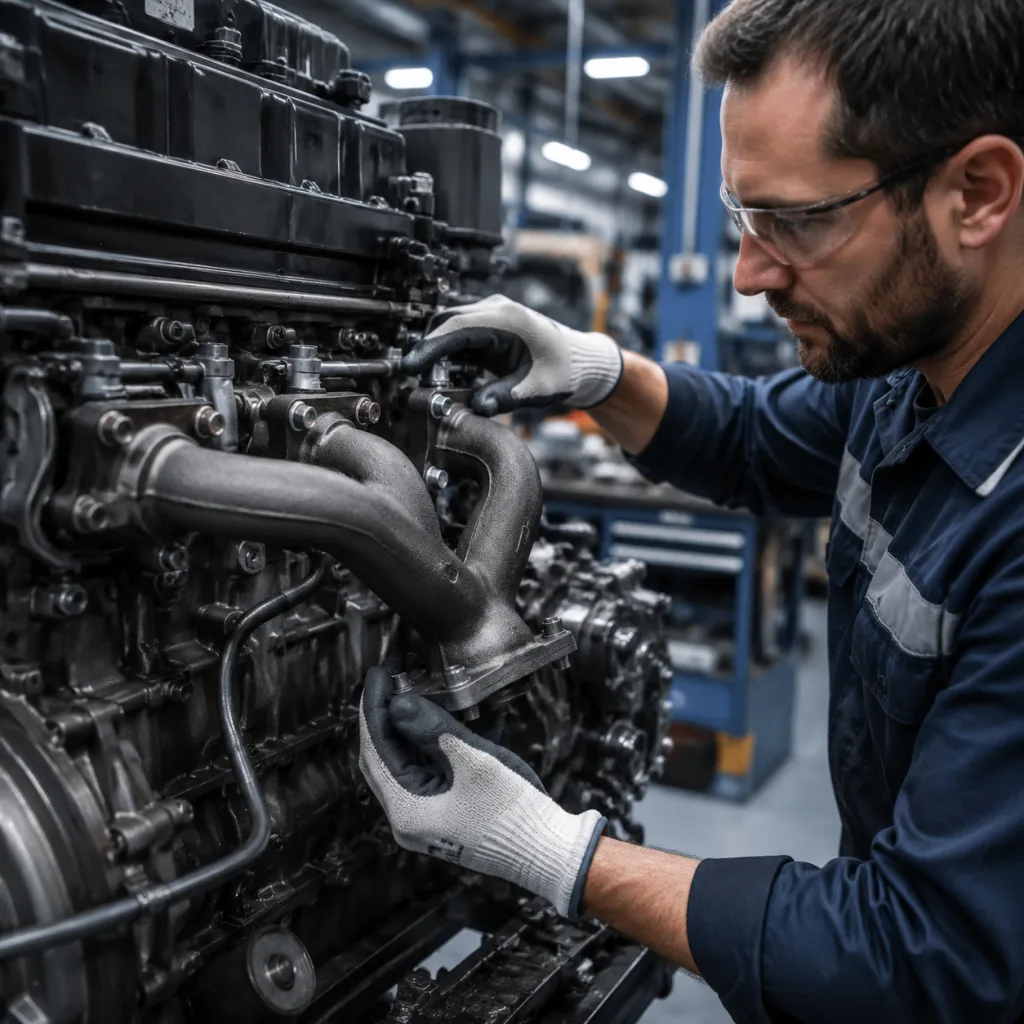
Exhaust Manifold How to Replace: Procedure Overview
The exact sequence depends on engine layout, turbocharger location, under-hood packaging, and emissions equipment. The following process is a general reference for maintenance planning and warranty review, not a substitute for vehicle service data.
1. Confirm the fault. Run the engine cold and listen for ticking near the head flange. Use smoke testing or a suitable leak detector where access is limited. Record any OBD faults related to oxygen sensors, catalyst efficiency, EGR flow, exhaust temperature, or turbo boost control. If possible, note whether the leak is present only on cold start or also after thermal expansion. 2. Allow safe cooldown and isolate power when required. A hot manifold can exceed 400 to 700°C at the surface in service. Follow workshop safety rules, especially where alternator wiring, starter cables, or oxygen sensor harnesses are near the work area. Disconnect the battery where the manufacturer or shop policy requires it. 3. Remove obstructing parts. This may include engine covers, intake ducting, heat shields, undertrays, EGR pipes, turbo oil/water lines, or the front pipe. Label electrical connectors and vacuum lines so reassembly is repeatable. If a bracket must be removed, note its orientation and any shim stack. 4. Treat fasteners before removal. Apply penetrating oil and allow dwell time. Use the correct six-point sockets to avoid rounding nuts. On heavily corroded vehicles, controlled heat may be required by trained technicians, but only when nearby hoses, wiring, and fuel components are protected. 5. Remove sensors and emissions connections. Oxygen sensors, EGT sensors, and EGR tubes are easily damaged. If a sensor is seized or its heater wiring is brittle, replacement may be lower risk than forcing removal. Mark sensor positions so bank and pre/post-catalyst locations are not mixed up. 6. Unbolt the manifold in a controlled sequence. Work progressively from the ends toward the center, or follow the OE sequence, to reduce stress on the casting and studs. If a stud breaks, repair the thread before fitting the new part; do not clamp a damaged hole and hope the gasket will compensate. 7. Clean and inspect mating surfaces. Remove gasket material without gouging the cylinder head. Check for pitting, pulled threads, flange distortion, and erosion around port edges. If the head face is damaged beyond the service limit, the new manifold may leak regardless of quality. 8. Trial-fit the new manifold. Confirm all ports, studs, heat-shield holes, brackets, and sensor bosses align before final assembly. A trial fit should reveal whether the part sits naturally without forcing, and whether adjacent components maintain at least the required clearance once the gasket is compressed. 9. Install new gaskets and fasteners. Tighten in the manufacturer’s sequence and stages. Many engines use an initial snug pass, then a second pass to final torque, and some use an angle-tighten step. Do not assume one torque value across engine families, and never reuse a torque-to-yield fastener unless the service data explicitly allows it. 10. Reassemble and test. Refit heat shields and connected systems, then run the engine through warm-up. Check for leaks, abnormal noise, fault codes, and contact between the manifold and surrounding components. After the first heat cycle, confirm there is no smoke, ticking, or witness mark from thermal expansion against nearby hardware.
For B2B documentation, a repair chain may convert these steps into a standard job card with required photos, torque sign-off, and a post-road-test inspection. A distributor can use the same checklist to handle technical support calls when a customer reports poor fitment or a cracked return part.
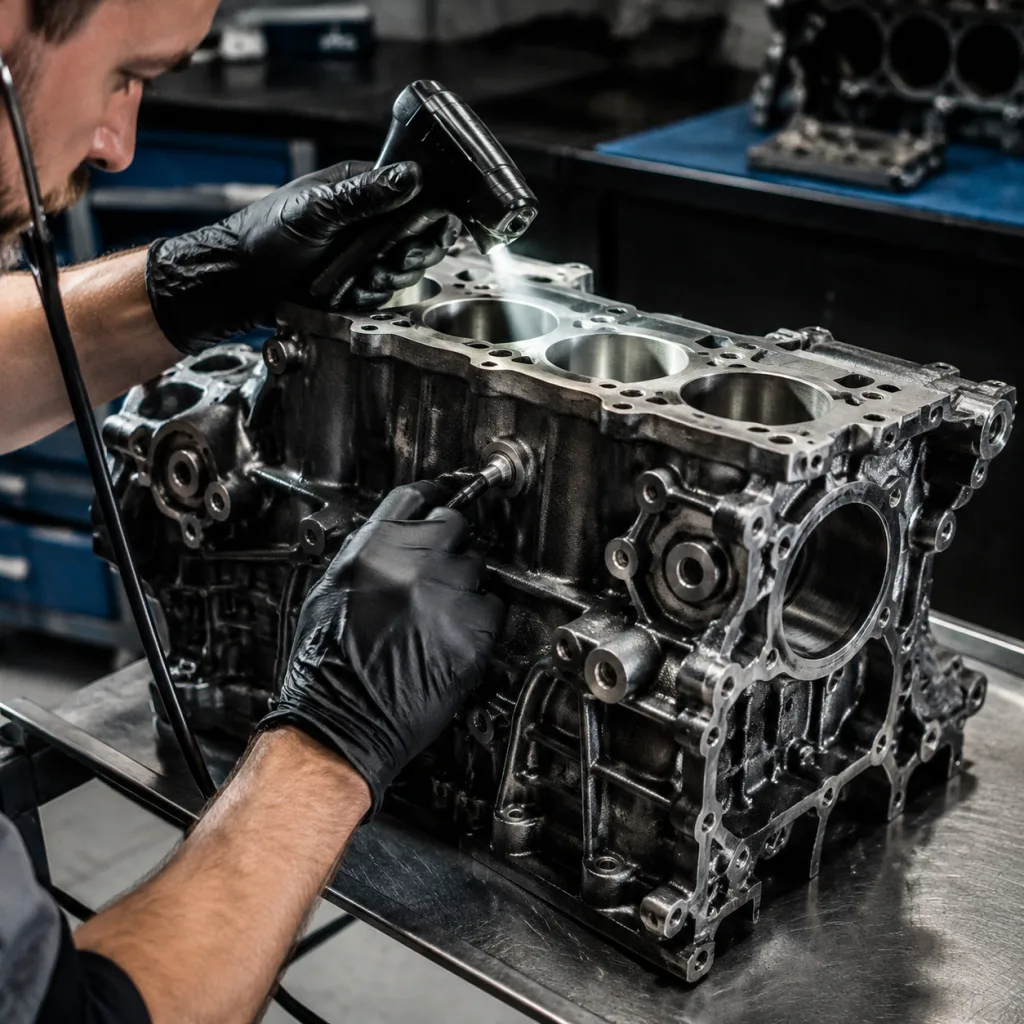
Dimensional and Material Checks for Replacement Parts
An aftermarket manifold should be assessed as an engineered component, not only as a visual match. The highest-risk areas are flange flatness, port position, threaded bosses, sensor bung angle, and heat-shield brackets.
Recommended inspection points for incoming quality control:
Cylinder head flange flatness: verify with a calibrated straightedge and feeler gauges; many buyers set an internal acceptance limit at 0.10 mm maximum deviation across the sealing face, or tighter if the OE requirement is lower.
Port alignment: compare to approved drawing, sample, or OE part-number cross-reference such as OE 06A… where applicable. Port offset or mismatch greater than 1.0 mm can disturb gasket compression and flow balance on some applications.
Thread quality: check oxygen sensor and EGR threads using gauges or validated mating parts. A correct bung should accept the sensor smoothly by hand for several turns before tool tightening.
Collector and runner wall condition: inspect for casting porosity, thin edges, weld undercut, incomplete machining, or excessive scale. Visible pinholes may be acceptable on non-sealing outer surfaces only if engineering review confirms no leak path.
Mounting bracket position: confirm heat-shield and support-bracket holes after thermal-stress design review. A bracket hole offset of even 2 to 3 mm can create assembly force and future cracking.
Surface condition: reject sharp gasket-face damage, loose scale, machining burrs, and contamination inside the runners.
Material verification: confirm alloy grade against the specification; cast parts often require high-silicon molybdenum ductile iron or comparable heat-resistant iron, while fabricated parts may use stainless grades chosen for temperature and corrosion resistance.
Mass and thickness consistency: compare sample weights and wall thickness with the approved master sample, since thin walls can crack early and overly thick sections may cause packaging or thermal issues.
Typical material options include high-silicon molybdenum ductile iron for high-temperature cast manifolds, grey iron for lower thermal-load applications, and stainless steel for fabricated tubular designs. The correct selection depends on exhaust gas temperature, turbocharger load, packaging, emissions calibration, and cost target. For a turbo diesel, buyers often prioritize thermal fatigue resistance and flange stability; for a naturally aspirated gasoline engine, cost and port accuracy may be the primary decision points.
Driventus applies production controls through its quality system, including dimensional inspection, material verification, and process traceability aligned to IATF 16949:2016 and ISO 9001:2015. For markets with chemical substance requirements, buyers may also request documentation relevant to REACH (EC) No 1907/2006. Where requested, a supplier should also provide first-article data, batch traceability, and a corrective-action response time for nonconforming lots.
Post-Installation Verification
A manifold can appear correctly installed and still fail after the first heat cycle if clamp load, connected components, or emissions hardware are not checked. Post-installation verification should be part of the labour standard.
Key checks include:
Start the engine cold and listen for exhaust pulses at the head flange.
Inspect around the manifold with a suitable light after warm-up and again after cool-down.
Confirm that oxygen sensor and EGT sensor wiring is routed away from hot surfaces and has enough slack for engine movement.
Check turbocharger oil and coolant lines if they were disturbed, and confirm there is no seepage at banjos or crimped lines.
Verify that heat shields are fitted and not contacting the manifold under vibration or engine roll.
Measure back-pressure, if the repair scope or vehicle data calls for it, to confirm no obstruction exists downstream.
Clear stored fault codes, then complete a drive cycle or workshop emissions readiness check where required.
Recheck accessible fasteners only if the vehicle service information instructs it; many fasteners are designed for a single final-torque event.
For regulated markets, manifold-related emissions performance must not compromise applicable vehicle obligations. Depending on application, buyers may need to consider emissions durability expectations associated with regulations such as ECE R-83. Do not remove or alter catalytic converters, oxygen sensors, EGR systems, or other emissions equipment unless local law and service information permit the work. If the vehicle returns with a repeat leak, capture cold-start audio, heat-cycle mileage, and flange condition so the source of failure can be separated from installation error.
Sourcing Notes for Distributors and Repair Chains
The phrase exhaust manifold how to replace often brings technicians to a procedure, but repeat-fitment success depends heavily on sourcing discipline. A correct replacement part should be supported by drawings, application data, inspection records, and stable packaging. The buying decision should also include MOQ, expected price bands, and lead-time control so the part can be stocked profitably without overcommitting cash.
When qualifying a supplier, request:
Application list by engine code, year range, emissions level, and body platform.
Cross-reference format, including generic OE references where legally and commercially appropriate.
Material grade declaration and casting or fabrication process description.
Critical dimension report for flange, port, boss, sensor, and bracket locations.
Heat-cycle or thermal-fatigue validation method for high-load applications.
Packaging specification for export cartons and palletisation.
Warranty analysis process for cracked, warped, or poor-fitment returns.
MOQ by part number, and whether mixed-model carton quantities are allowed for launch stocking.
Ex-works or FOB price breaks by annual volume, because a price that improves only above a certain tier may affect distributor margin.
Standard lead time, expedited lead time, and the cutoff for production slots, so reorder points can be set realistically.
Useful commercial logic for buyers:
For slow-moving SKUs, a higher unit price may be acceptable if MOQ is low, because carrying cost can exceed the savings from a larger order.
For high-failure fleet applications, ask for a buffer stock agreement or rolling forecast so replenishment does not exceed a 4 to 8 week supply gap.
If the supplier quotes a 2 to 4 week lead time for castings but 6 to 8 weeks for first tooling or process changeovers, separate launch timing from steady-state replenishment in the contract.
Define acceptance on sample builds before placing volume orders, including one or two trial cartons for fitment confirmation, not just catalog approval.
Driventus supplies exhaust manifolds as part of our catalog and broader engine components. For private-label programs, drawing-controlled parts, or application expansion, our engineering team can support custom manufacturing based on samples, 3D data, or buyer drawings. If your team is building a sourcing plan, you can also request a quote with target applications, annual volume, target MOQ, required packaging, and inspection requirements.
Frequently asked questions
It is not recommended. Exhaust manifold gaskets are compressed and heat-cycled in service. Reuse can lead to leakage, noise, and repeat labour claims. Replace gaskets and any fasteners specified by the vehicle service information. In practice, a shop should also inspect the sealing face and studs before fitting the new gasket so the replacement is not compromised at installation.
Common causes include warped cylinder head faces, damaged gasket surfaces, reused fasteners, incorrect torque sequence, misaligned brackets, a missing heat shield, or a part with poor flange flatness. Incoming inspection and correct workshop procedure both matter. A leak that appears only after the first heat cycle often points to uneven clamp load or a flange that moved under thermal expansion.
Driventus is an independent aftermarket manufacturer; brand names are referenced for fitment only. We do not claim vehicle manufacturer approval. We manufacture to buyer specifications with quality controls aligned to IATF 16949:2016 and ISO 9001:2015.
For application coverage, drawings, samples, MOQ, lead-time, or distributor quotation support, contact Driventus with your target part family and annual demand. Start here: /contact.html