Engine stalling at idle creates two problems at once: an unresolved vehicle fault and a parts return that may not be a parts failure. For distributors, repair chains, fleet workshops, and sourcing engineers, the expensive case is familiar: the vehicle receives an idle air control valve, throttle body, fuel pump, gasket, or sensor, then comes back with the same stall.
The fix is not to guess faster. It is to separate the stall into evidence categories: air metering, vacuum integrity, fuel delivery, ignition stability, ECU input, emissions hardware, and mechanical sealing. This guide reframes engine stalling at idle causes and fixes as a diagnostic and sourcing decision tool, using practical checks such as fuel trims, vacuum readings, fuel-pressure decay, signal dropouts, compression spread, and warranty evidence requirements.
It also shows where component quality affects field performance in aftermarket supply programs. Driventus manufactures engine and powertrain components in Taizhou, Zhejiang, under IATF 16949:2016 and ISO 9001:2015 systems for B2B aftermarket and OEM supply programs. Driventus is an independent aftermarket manufacturer; brand names are referenced for fitment only.
Decision Framework: Match the Stall Pattern Before Ordering Parts
Start with the moment the engine dies. A cold-start stall, warm-idle stall, load-related stall, and random cut-out do not deserve the same first test. If a workshop replaces the most visible part before classifying the pattern, the return rate usually rises.
Use the intake form as a diagnostic control point. It should capture coolant temperature at start, ambient temperature, closed-loop status, commanded idle speed, actual RPM, STFT, LTFT, battery voltage, recent refuelling, A/C load, steering input, and whether the stall occurs within 5 seconds, within 30 seconds, after warm-up, or when shifted into drive. For warranty screening, require a freeze-frame screenshot or scan-tool log. A written symptom description is not enough.
Stall pattern
Diagnostic direction
First checks
Practical trigger point
Cold start, then dies
Air bypass, enrichment, coolant temperature input
Scan data, idle command, intake deposits
ECT more than ±5 °C from ambient after overnight soak
Warm idle stall
Vacuum leak, EGR leakage, fuel pressure drop
Fuel trim, smoke test, fuel pressure
STFT + LTFT above +10% at idle and lower at 2,500 rpm
Stalls with A/C or steering load
Idle control response, alternator load, throttle adaptation
Load compensation data, charging voltage
RPM drop over 150–250 rpm without recovery in 2 seconds
Stalls when shifted into drive
Torque converter load, low idle control margin, engine mounts
RPM drop, transmission load data
In-gear idle below OEM target by more than 75–100 rpm
Random idle cut-out
Crankshaft signal, ignition power supply, relay or ground fault
RPM signal, oscilloscope trace, harness checks
Tach or scan RPM drops to zero before engine stops
</tr></thead><tbody> </tbody></table>The rule is simple: idle stability is a balance between measured air, unmetered air, injected fuel, spark timing, electrical supply, and mechanical compression. The same customer complaint can come from a leaking intake gasket, a weak pump, a crank signal dropout, or one low-compression cylinder.
For B2B programs, classify every idle-related claim by evidence: air leak confirmed, fuel pressure low, signal dropout, mechanical low compression, installation damage, or no fault found. After 50–100 claims, the pattern usually shows whether the issue is part quality, catalog fitment, installation practice, or incomplete diagnosis.
Failure Mode Deep-Dive: Unmetered Air, Vacuum Leaks, and Throttle Deposits
Unmetered air is a leading cause of idle stall because a small leak becomes a large percentage of total airflow at closed throttle. A split intake hose, leaking manifold gasket, brake booster leak, PCV fault, distorted throttle-body seal, or loose duct after the mass airflow sensor can push the ECU into the wrong fuel calculation. The result may be lean idle, hunting RPM, extended cranking, or a stall immediately after start-up.
A useful inspection sequence is short and evidence-led:
Compare STFT and LTFT at hot idle and at 2,500 rpm with no load. Combined trim above +10% suggests a lean condition; above +20% usually requires leak or fuel-pressure testing before sensor replacement.
Smoke-test the intake tract, vacuum hoses, PCV circuit, brake booster line, purge line, manifold joints, injector seals, and throttle-body gasket. Use 0.5–1.0 psi for most intake smoke tests to avoid dislodging seals.
Measure intake manifold vacuum where applicable. A steady 17–22 inHg at warm idle is typical for many naturally aspirated gasoline engines. Low or unstable vacuum points to leakage, valve timing, or mechanical faults.
Inspect throttle plate deposits and confirm whether cleaning requires electronic throttle adaptation. Many electronic throttle systems need a scan-tool reset or idle relearn after cleaning.
Check idle air control valve movement on older cable-throttle systems. A sticking pintle, carbon restriction, or worn stepper motor can block the ECU from adding bypass air.
Inspect intake manifold and throttle-body gaskets for compression set, hardening, cracking, oil swelling, and imprint loss. Rubber that stays flattened after removal is a field-risk signal.
Fuel trim behaviour separates many cases. If trims are high at idle and improve as RPM rises, smoke testing and gasket inspection move to the front. If trims stay lean under load, fuel delivery deserves priority.
For procurement teams, sealing material is not a commodity detail. Intake gaskets and related rubber parts should define material family such as NBR, FKM, ACM, or silicone according to fluid and temperature exposure; operating temperature range; hardness target, commonly Shore A ±5; critical thickness tolerance, commonly ±0.10–0.20 mm depending on design; compression set after ageing; and visual criteria for flash, parting lines, and contamination.
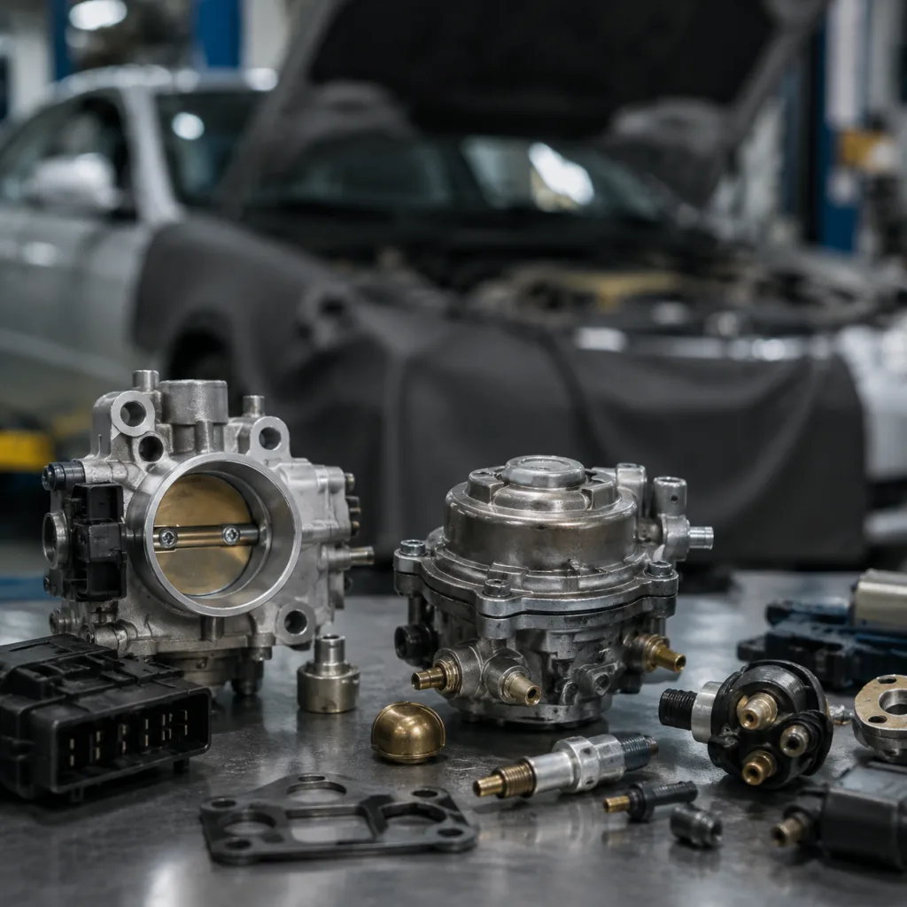
Throttle-body and machined intake parts need checks for bore size, flatness, shaft play, actuator response, and cleanliness. For high-volume programs, ask suppliers for 100% visual inspection on sealing faces, CMM or gauge records for critical dimensions, and batch traceability by cavity, mould, heat number, or machining lot where applicable. Driventus supplies gaskets, throttle-related machined parts, and engine components through our catalog, with process control linked to our documented quality system.
Comparison Test: Fuel Delivery Fault or Ignition Dropout?
Fuel and ignition faults both become obvious at idle because combustion reserve is low. The engine is turning slowly, airflow is limited, and a small weakness can stop recovery after an RPM dip. A weak fuel pump, restricted filter, poor injector spray pattern, contaminated rail, ageing spark plug, unstable coil, or weak ground can all look like the same stall to the driver.
Do not treat a pressure reading as the whole fuel test. Include static pressure, running pressure, pressure decay after shut-off, volume delivery, and pump current where access allows. Always compare with the vehicle specification, but many gasoline port-injection systems operate around 3.0–4.0 bar, while gasoline direct-injection low-pressure supply may be around 4–6 bar before the high-pressure pump. A pressure drop of more than 5–10 psi within 5 minutes after shut-off can indicate a leaking injector, regulator, check valve, or internal pump issue, depending on system design.
On returnless systems, compare commanded and measured rail pressure. A healthy pump should follow demand without excessive current draw, noise, or pressure ripple. If pressure is marginal, test voltage at the pump under load. A 0.5 V drop across a poor connector or ground can reduce flow enough to affect idle recovery. Injector balance testing is useful when one cylinder contributes less at idle but appears normal at higher RPM; cylinder-to-cylinder delivery variation above 5–10% should trigger cleaning, replacement, or rail contamination checks.
Ignition diagnosis should cover secondary ignition patterns, coil dwell command, spark plug condition, coil boot tracking, battery condition, charging voltage, and ground integrity. At warm idle, charging voltage is commonly 13.5–14.7 V on many systems, though smart charging strategies vary. Stability under fan, A/C, lighting, and steering load matters more than one unloaded number. Cranking voltage below about 9.6 V on a 12 V system can corrupt idle relearn or sensor reference behaviour. Loaded voltage drop on main grounds and power feeds should usually stay below 0.1–0.2 V.
Intermittent stalls need a time-based signal view, not just stored codes. A crankshaft or camshaft position signal dropout may cut the engine without storing a permanent code. Use an oscilloscope or graphing scan tool to compare crank, cam, injector pulse, ignition command, and RPM signal during the stall. If scan RPM falls to zero before mechanical rotation stops, prioritise the crank signal or ECU power supply.
Relevant sourced parts include fuel pumps, injectors, ignition-related housings, crankshaft sensors, camshaft sensors, connectors, and engine sealing parts. Validation should include thermal cycling, vibration exposure, connector retention checks, winding resistance or signal checks where applicable, and end-of-line electrical testing. Acceptance files should include flow and pressure curves for pumps, leakage and spray pattern records for injectors, resistance or Hall-signal checks for sensors, connector insertion and retention force, and packaging drop-test confirmation for export cartons.
Q&A Checkpoint: Sensors, ECU Inputs, and Emissions Hardware
Which sensor values should look believable before any part is replaced?
After an overnight soak, coolant temperature and intake air temperature should usually sit within ±3–5 °C of ambient. Throttle position should move smoothly without dropouts, dead spots, or sudden percentage jumps. Mass airflow should rise proportionally with RPM; as a quick sense check, many warm gasoline engines read roughly 2–7 g/s at idle depending on displacement and load. MAP readings should reflect manifold vacuum changes, with lower kPa at closed throttle and higher kPa when the throttle opens. Oxygen sensor activity should be judged only after closed-loop operation begins.
What circuit checks prevent false sensor diagnosis?
Check the 5 V reference circuit, sensor ground, signal return, connector fit, terminal tension, and harness movement. A rubbed-through 5 V reference wire can make several unrelated sensors appear faulty. For intermittent stalls, gently load the harness while watching live data. A sudden coolant temperature jump, throttle-position spike, or RPM dropout is more useful than a stored code with no context.
How can emissions hardware stall an engine at idle?
An EGR valve that does not fully close can dilute the idle mixture with exhaust gas. Even a small leak may cause rough idle on engines not designed for EGR flow at idle. A purge valve stuck open can introduce excess fuel vapour at idle, especially after refuelling or hot soak. A basic purge check is to command the valve closed, clamp or isolate the line where safe, and observe whether fuel trims and idle stability improve. These systems are relevant to vehicles certified under emissions frameworks such as ECE R-83 in many markets. Replacement parts must support the repair objective without implying vehicle manufacturer approval.
What should buyers specify for sensors and emissions-related parts?
Request electrical pinout confirmation, signal range, response-time target, leakage rate where applicable, operating temperature range, salt-spray or corrosion requirement for exposed connectors, and end-of-line test method. Purge valves should define closed-state leakage, coil resistance tolerance, flow rate at specified duty cycle, and connector keying. MAP and position sensors should be checked across multiple temperature points, not only at room temperature.
When a vehicle platform requires market-specific configuration, Driventus can support custom manufacturing for B2B programs, including drawings, material selection, packaging requirements, application documentation, PPAP-style records where required, and production traceability by batch.
Scenario: When an Electronic-Looking Stall Is Mechanical
A high-mileage fleet vehicle arrives with a warm idle stall. The throttle body has already been cleaned. A sensor has been replaced. The fault remains. At this point, the diagnostic path should widen: not every idle stall is caused by electronics or fuel control.
Low compression, incorrect valve timing, worn piston rings, leaking head gasket, poor valve sealing, intake valve deposits, or excessive crankcase ventilation flow can create idle instability that does not respond to sensor replacement. This is common in older engines, high-mileage fleets, and markets where repair quality varies by workshop.
Mechanical checks should include:
Compression testing and, where needed, cylinder leak-down testing. Many gasoline engines should show cylinder variation within about 10–15%; a single weak cylinder can cause idle stall even if average compression appears acceptable.
Timing belt or chain alignment inspection, including cam/crank correlation data where supported by the scan tool. One tooth of timing error can look like a sensor, throttle, or mixture problem.
Crankcase vacuum or pressure measurement. Excessive blow-by or a failed PCV valve can upset idle airflow and contaminate the intake tract.
Cooling system pressure testing if coolant loss, overheating, misfire at start-up, or white exhaust smoke is present. Pressure loss can indicate head-gasket, casting, hose, or water-pump sealing issues.
Inspection for oil contamination around intake ducts, throttle body, intercooler pipes, and PCV paths. Oil film can change airflow measurement and collect dust around the throttle plate.
Vacuum gauge observation where applicable. A bouncing needle may indicate valve sealing issues; a low steady reading may indicate late valve timing, intake restriction, or leakage.
If compression is low, valve timing is wrong, or coolant intrusion is present, replacing idle-control, fuel, or sensor components will not solve the fault. Engine repair may require pistons, piston rings, head gaskets, valve components, water pumps, timing components, or crankshaft-related parts. For turbocharged engines, also inspect charge-air leaks, diverter valves, and oil contamination that can affect idle after deceleration.
For importers and wholesalers, this broader fault range changes stocking logic. A stall complaint may create demand across diagnostics, fuel, ignition, sealing, cooling, and core engine components rather than one SKU category. Catalog depth, fitment accuracy, and batch traceability determine how quickly repair networks can close these cases.
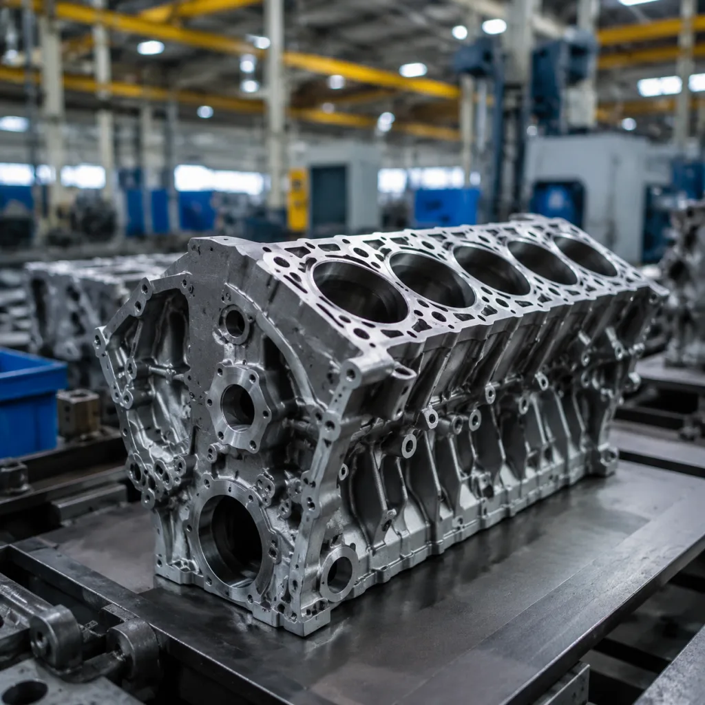
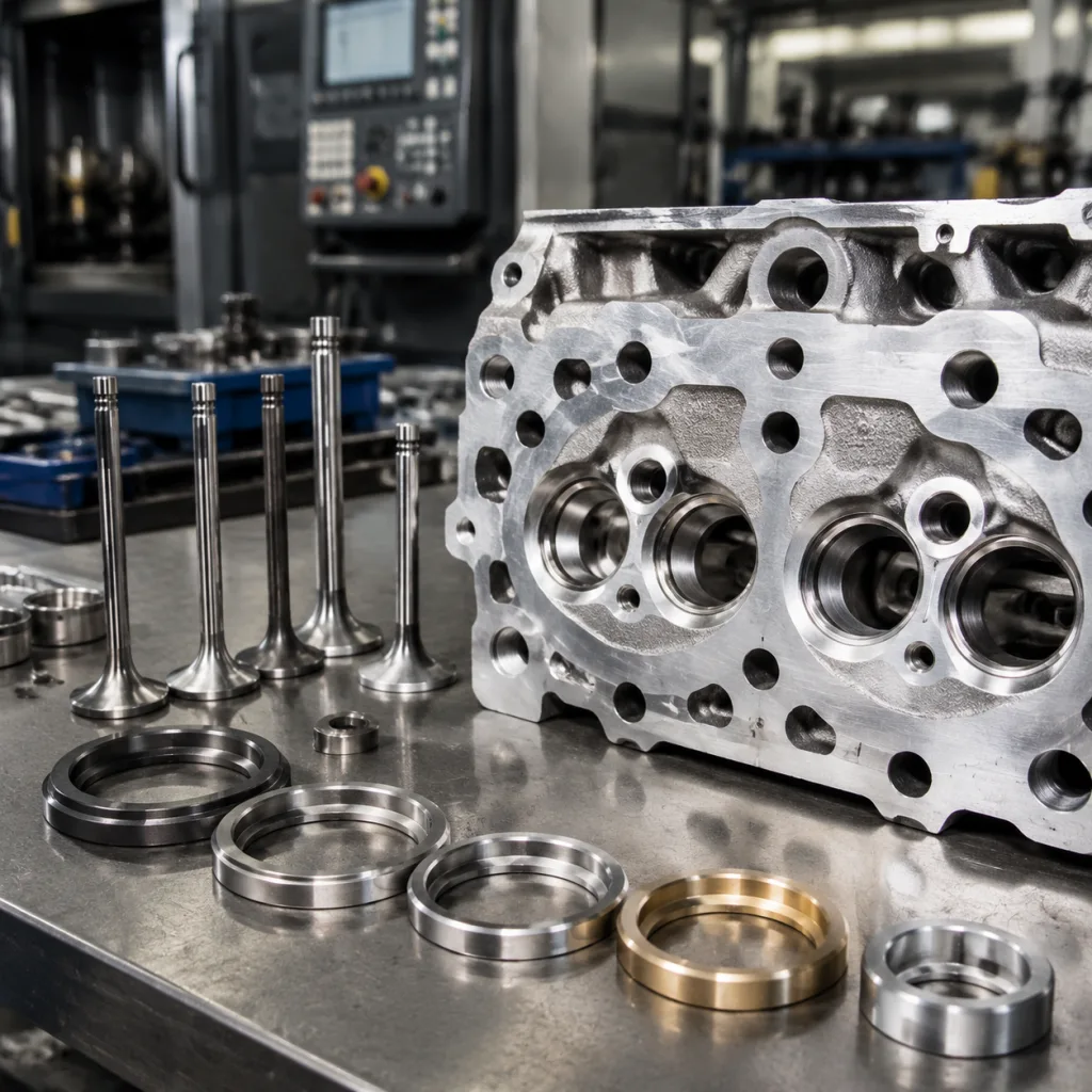
Mechanical parts need tighter sourcing discipline than visual fitment. Pistons and rings should define alloy, coating, ring gap range, groove clearance, and dimensional tolerance. Head gaskets should define bore diameter, thickness, coating type, embossment integrity, and surface finish requirements. Water pumps should define bearing play, seal leakage test, impeller material, flow performance, and pulley runout. Reject samples that fit the engine but lack measurable production controls.
Step-by-Step Fix Strategy and Supplier Acceptance Criteria
The correct fix follows the confirmed cause. Clean and adapt the throttle body when deposits restrict airflow. Replace cracked hoses or hardened gaskets when smoke testing confirms leaks. Replace fuel pumps, injectors, coils, sensors, or crankshaft-related components only after measured data supports the decision. For repeat failures, inspect wiring, grounds, connector fit, battery condition, charging voltage, and ECU software or adaptation status before approving another part claim.
A practical repair sequence is:
1. Document the symptom and operating condition. 2. Scan for codes and freeze-frame data. 3. Verify battery and charging health. 4. Compare trims and commanded idle. 5. Smoke-test the intake. 6. Measure fuel pressure and pressure decay. 7. Check ignition stability and RPM signal. 8. Review sensor plausibility. 9. Perform compression or leak-down testing if electronic and fuel checks do not confirm the cause.
This order prevents common misdiagnosis, especially replacing MAF sensors, idle valves, or throttle bodies before an intake leak or low fuel pressure is proven.
For B2B sourcing, idle-related components should be evaluated with both dimensional and functional criteria:
Part type
Key procurement checks
Suggested measurable requirement
Field risk if uncontrolled
Gaskets and seals
Material compatibility, compression set, thickness tolerance
Shore A ±5, critical thickness ±0.10–0.20 mm, ageing and oil-resistance test
Vacuum leaks, repeat idle stalls
Fuel pumps
Flow rate, pressure curve, current draw, noise
100% end-of-line pressure/flow test, current within approved range, leak check
Lean idle, hard start, stall under load
Sensors
Signal range, connector fit, thermal stability
Pinout verification, hot/cold signal test, terminal retention check
False ECU input, intermittent cut-out
Throttle components
Bore accuracy, actuator response, cleanliness
Bore and flatness gauges, actuator response test, clean packaging
Idle hunting, adaptation failure
Engine parts
Machining tolerance, surface finish, material traceability
CMM or gauge records, Ra requirement, heat/batch traceability
Low compression, oil consumption, overheating
</tr></thead><tbody> </tbody></table>Agree MOQ, price, and lead-time logic before sampling. For existing aftermarket SKUs with active tooling, trial orders often start around 100–300 pieces per SKU for sensors, gaskets, and small machined parts; pumps or complex assemblies may require 50–200 pieces depending on test load and component cost. New-tool or custom parts normally need higher economic quantities, often 500–1,000+ pieces per SKU, because tooling, fixtures, packaging, and validation must be amortised. Final MOQ depends on raw material batch size, mould cavities, machining setup time, test cycle time, and packaging configuration.
Evaluate price as landed, validated cost rather than unit price only. A low quote that excludes end-of-line testing, export carton strength, connector validation, traceability labels, or restricted-substance documentation can create higher warranty cost. Compare EXW/FOB terms, tooling charge, sample charge, carton quantity, HS code, target annual volume, payment terms, and warranty reserve assumptions. Mature stocked SKUs usually quote faster and lower; custom tooling, low annual demand, or multi-market labelling increases cost and lead time.
Typical lead-time planning is 7–15 days for catalogue sample dispatch when inventory or near-finished stock exists, 25–45 days for first production after sample approval on active tooling, and 45–90+ days for new-tool development depending on drawings, validation, and PPAP-style documentation needs. Add time for material confirmation, fitment cross-checking, carton artwork, private-label approval, and pre-shipment inspection. Urgent replenishment is realistic only when tooling, materials, and test capacity are already reserved.
Warranty review should include the diagnostic record. A returned part with no pressure reading, scan data, smoke-test result, or electrical measurement is difficult to classify. Minimum claim evidence should include VIN or application, mileage, installation date, fault code and freeze-frame data, measured pressure or signal where relevant, photos of connector and mounting condition, and return batch code.
Driventus production controls are aligned with IATF 16949:2016 and ISO 9001:2015. Material and restricted-substance requirements can be managed for applicable markets under REACH (EC) No 1907/2006. For brake-related sourcing programs, test references such as SAE J2527 may apply, but idle-stalling diagnostics generally concern engine, fuel, ignition, sensor, sealing, and mechanical systems. Buyers can review product families through our catalog or request a quote for application-specific supply discussions.
Frequently asked questions
Common causes include unmetered air from vacuum leaks, dirty throttle bodies, weak fuel delivery, ignition instability, incorrect sensor inputs, and mechanical compression problems. A practical first screen is combined fuel trim at idle: if STFT plus LTFT is above +10% and improves at 2,500 rpm, smoke-test the intake before replacing sensors.
Yes. A leaking intake manifold, throttle-body, injector, or related vacuum gasket can admit unmetered air. This may create a lean mixture at idle and cause rough running or stalling. Heat-aged, cracked, oil-swollen, or permanently compressed materials are frequent contributors in high-mileage vehicles.
Distributors can reduce returns by requiring measured fault evidence for warranty claims, such as scan data, fuel-pressure readings, smoke-test results, signal checks, photos, and batch codes. They should also source components with controlled material, dimensional, electrical, and functional validation, not fitment appearance alone.
For validated engine, fuel, ignition, sealing, and diagnostic-related components, contact Driventus with your application list, target market, annual volume, target MOQ, packaging requirement, and required lead time. Start a sourcing discussion at /contact.html