Camshaft Porsche Aftermarket Replacement: OE Match Criteria
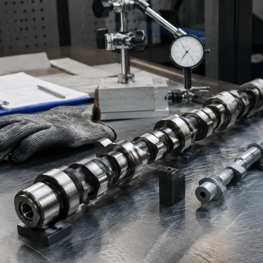
A camshaft Porsche aftermarket replacement has to match the engine’s operating geometry, not just the visible profile of the original part. For procurement teams, the critical checks include lobe lift, base-circle diameter, journal size and position, timing phasing, thrust features, surface finish, hardness, and material condition against the target engine code and OE reference. In Porsche flat-six and other performance-oriented applications, even small deviations can affect valve events, idle quality, emissions behaviour, oil-film stability, and long-term wear. Driventus supplies engine components for B2B replacement programmes with inspection records managed under IATF 16949:2016 and ISO 9001:2015 quality controls. Driventus is an independent aftermarket manufacturer; brand names are used for fitment identification only. This guide explains the evidence to review before sourcing, the validation data that helps prevent returns, and the supplier controls needed for consistent fitment across EU, UK, US, Canadian, Australian, and Brazilian markets.
Decision check: is it truly OE-equivalent?
A camshaft Porsche aftermarket replacement only works as a procurement-safe option when it preserves the operating geometry the engine expects. That means the question is not “does it look right?” but “does it match the engine code, OE reference, and measurable specification?”
Key items to verify include:
- OE part-number cross-reference where available, and only when the target listing already uses that reference, such as `OE 06A107065`
- Journal diameter, journal width, and overall length within the stated production tolerance
- Lobe lift, duration, ramp profile, and lobe separation matched to the intended engine variant
- Base-circle diameter and nose profile consistent with the valve-train design
- Cam timing features, drive interface, dowel location, sensor trigger features, and thrust-face design
- Nose hardness, case depth, and core material condition after heat treatment
- Surface roughness on journals and lobes, with a controlled finish to support oil retention and reduce break-in wear
- Straightness, total indicated runout, and concentricity checked on calibrated fixtures
The supplier should also state the delivery condition of the part: raw blank, semi-machined component, finish-machined camshaft, or fully heat-treated and ground assembly-ready item. That distinction changes the inspection scope, responsibility split, lead time, and landed cost. For distributor programmes, it also determines whether your team must perform additional finishing, coating, or final inspection before sale.
Failure modes buyers should screen out
Most camshaft sourcing problems do not start with a visible defect. They start with a small mismatch that passes a quick visual check and fails later in the engine.
Typical failure modes include:
- Incorrect base-circle diameter, which changes valve lash and follower position
- Lobe phasing drift, which moves valve events away from the target timing window
- Journal spacing errors, which create assembly stress and bearing wear
- Thrust-face or end-play mismatch, which allows axial instability
- Drive or sensor feature mismatch, which can break timing accuracy or ECU signal compatibility
- Weak heat treatment, which shows up later as lobe wear or journal scoring
- Poor surface finish, which slows oil-film formation and increases break-in wear
- Runout or concentricity issues, which contribute to NVH and premature fatigue
These are the defects that generate returns, not because the camshaft is obviously wrong, but because it behaves wrong once installed. For that reason, a supplier claim is not enough; the part needs measurement evidence tied to the exact engine family and the intended OE reference.
Comparison table: what to verify and why
Replacement sourcing is most reliable when the technical review begins with the engine code, OE reference, and application notes, then moves to measurable evidence. Build a comparison file that records the supplier’s stated specification, your sample measurements, and any drawing or reference data available.
| Check item | What to verify | Why it matters |
|---|---|---|
| Base-circle diameter | Compare with OE drawing, approved sample, or reverse-engineered reference | Sets valve lash, follower position, and timing geometry |
| Lobe lift | Measure every lobe and compare across the shaft | Controls airflow, combustion behaviour, and engine output |
| Lobe phasing | Confirm angular position relative to the timing reference | Prevents valve-timing error and drivability issues |
| Journal spacing | Check centre-to-centre positions and journal widths | Prevents assembly stress, timing drift, and bearing wear |
| End play features | Confirm thrust face, groove, and stop design | Affects axial stability and oil control |
| Drive and sensor features | Verify gear, slot, keyway, dowel, or trigger geometry | Ensures correct installation and ECU signal compatibility |
| Heat treatment | Request hardness range, case depth, and test locations | Supports wear resistance at lobes and journals |
| Surface finish | Review roughness values for lobes and bearing surfaces | Helps manage break-in wear and oil-film formation |
| Dynamic balance or runout | Ask for test method, fixture, and limits | Reduces NVH, bearing load, and premature wear risk |