camshaft · 2026-06-02

Camshaft for Opel Corsa Aftermarket Replacement

A camshaft for Opel Corsa aftermarket replacement should be specified from engine data and functional geometry, not from the Corsa name alone. Across Opel Corsa generations, applications can change by engine code, displacement, fuel type, valve count, camshaft position, timing-belt or timing-chain drive, cam sensor target design, cylinder-head casting, and follower type. Two vehicles with the same badge may still need different journal spacing, lobe phasing, thrust control, nose geometry, or ECU synchronisation features.

Driventus is an independent aftermarket manufacturer; Opel and Corsa names are used only for fitment identification. For distributors, wholesalers, engine rebuilders, and repair-network buyers, the sourcing question is practical: will the replacement camshaft match OE functional dimensions every time? That means checking whether journal diameter, lobe lift, base circle, runout, and trigger indexing are measured against an approved reference, and whether hardness, surface finish, corrosion protection, batch traceability, and packaging identification are documented before shipment.

This page explains how to specify an OE-equivalent replacement camshaft, which dimensional and material checks to review before release, how production is controlled under IATF 16949:2016 and ISO 9001:2015, and what validation records procurement teams should request before committing to a lot. See our catalog for related timing parts and engine components for the broader range.

What to confirm before you order

Order a replacement camshaft from verified application data, not from the vehicle nameplate or a brief catalogue note. Opel Corsa fitment can vary by engine code, displacement, fuel system, emission calibration, cylinder count, valve-train layout, and follower design, including hydraulic tappets, mechanical followers, rocker arms, roller followers, or direct-acting buckets. Buyers should also confirm whether the part is an intake camshaft, exhaust camshaft, or combined single overhead camshaft, and whether the engine uses SOHC or DOHC architecture.

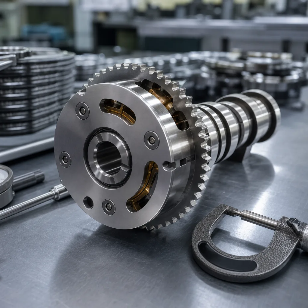
The basic fitment check should cover engine code, production year range, camshaft position, bearing journal count, journal order, drive method, thrust-control location, and any sensor or phasing features machined into the shaft. For timing-drive compatibility, confirm whether the camshaft uses a sprocket, pulley, gear, or chain-drive interface. Then verify the fastening pattern, locating dowel, keyway, taper, bolt thread, nose length, and sprocket seating face. For ECU compatibility, identify the reluctor, vane, slot, drilled trigger, pressed ring, or machined timing target read by the camshaft position sensor.

The target is OE-equivalent installation with no extra machining, shimming, spacing, or adaptation. To get there, the cam profile, overall length, journal locations, thrust face, nose geometry, rear-end feature, oil-feed details, and sensor target must match the intended cylinder head and engine management system. Even a small lobe-indexing or trigger-position error can move valve timing or synchronisation far enough to cause hard starting, cam/crank correlation fault codes, unstable idle, emissions failure, misfire detection, or a no-start condition.

Treat packaging and catalogue identification as part of the specification, not an afterthought. Each box should identify the application clearly enough for distributors, warehouse teams, and workshops to separate similar Corsa engine families. For resale stock, include part number, batch number, engine-code coverage, camshaft position where relevant, barcode or QR code, cross-reference control, and orientation photos where similar shafts are stocked together. Good identification reduces mixed-stock errors and allows any field issue to be traced back to a defined production lot.

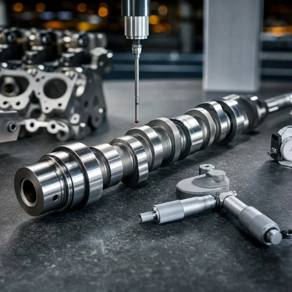
Dimensional checks that prevent returns

The most reliable way to avoid a mismatch is to compare the finished camshaft with a verified OE sample, approved drawing, or customer-supplied technical file. Catalogue cross-reference alone is not enough for a camshaft for Opel Corsa aftermarket replacement, because many critical features are hidden once the part is boxed and are difficult to verify at the workshop counter. Buyers should ask for measurement data before release, especially when launching a new SKU, changing supplier, or consolidating several references into one programme.

</tr></thead><tbody> </tbody></table>When a full engineering drawing is unavailable, request a confirmed sample measurement report and agree the critical-to-function features before production release. The report should state the inspection method, measuring equipment, datum scheme, sampling level, and acceptance criteria. For procurement teams, that discipline is usually far cheaper than handling a field return, workshop labour claim, or market-wide stock correction.

Separate launch inspection from routine batch inspection. Launch inspection should compare every critical feature against the approved sample or drawing, including angular features that are easy to miss in a basic dimensional report. Routine batch inspection can then focus on the dimensions most likely to affect installation, timing accuracy, oil clearance, sealing, and durability, while keeping records tied to the batch number printed on the packaging.

Materials and machining control

A camshaft for a small-displacement Opel Corsa engine may be produced from chilled cast iron, ductile iron, forged steel, or alloy steel, depending on the OE design, follower type, engine speed range, and required surface performance. The material name alone does not tell the full story. Buyers should look at the complete process route: blank control, machining sequence, heat treatment, rough and finish grinding, straightening, deburring, washing, corrosion protection, and final inspection.

For lobe and journal durability, ask for the material grade, hardness range, case depth or chilled-layer characteristics where applicable, and the finishing method used on working surfaces. Lobe hardness must be compatible with the follower material and contact pattern; excessive hardness mismatch can accelerate scuffing, while insufficient surface hardness can cause pitting or lobe wear. Journal hardness and finish must support stable oil-film operation without damaging aluminium cylinder-head bearing surfaces or replaceable bearing shells where used. If the camshaft is induction hardened, chilled, nitrided, carburised, or otherwise treated, the supplier should state the controlled process and acceptance range.

Machining control matters just as much as material choice. Journal concentricity, lobe-to-datum angle, nose geometry, thrust-face squareness, seal-land finish, and sensor-trigger position all depend on stable fixtures, controlled grinding wheels, verified datums, and in-process checks. A visually clean camshaft can still be wrong if the lobe phasing is outside tolerance or the trigger feature is indexed incorrectly. Finished shafts should be deburred, magnetically or visually inspected according to the agreed control plan where applicable, cleaned of abrasive residue, and protected from dents and corrosion. Small marks on a lobe, journal, or seal land can affect break-in performance.

For chemical compliance, material declarations should support REACH (EC) No 1907/2006 where required by the destination market. For production control, Driventus manufactures under IATF 16949:2016 and ISO 9001:2015, with batch traceability tied to inspection records, packaging identification, controlled production documentation, and shipment records.

If you need non-standard lobe timing, revised sensor phasing, an application consolidation review, or a private-label programme, custom manufacturing is available for defined drawings and confirmed volumes. In those cases, the drawing should identify all critical-to-function dimensions, datum references, required material and surface treatment, inspection frequency, packaging requirements, corrosion-protection method, and any market-specific compliance needs before tooling or production release.

Validation data buyers should request

A sensible release package should be practical, repeatable, and easy for purchasing, quality, and technical teams to review. It does not need to be overloaded, but it should prove two things: the camshaft matches the intended application, and future batches can be checked against the same standard. For a camshaft for Opel Corsa aftermarket replacement, the release evidence should connect the part number, engine-code coverage, drawing or sample reference, inspection data, production batch, and packing identification.

At minimum, request:

  • Material specification and heat-treatment or surface-treatment declaration
  • Dimensional inspection report for journals, lobes, drive interface, sensor features, end features, thrust face, and overall length
  • Lobe lift, base circle, and phasing confirmation against the approved reference
  • Runout record for the finished shaft, including datum locations and measuring method
  • Hardness result for lobes and journals where specified by the process route
  • Surface finish and visual acceptance criteria for lobes, journals, seal lands, edges, nicks, scoring, burrs, and corrosion
  • Batch traceability linked to production date, inspection records, operator or line record where applicable, and packing identification
  • Packaging specification suitable for export storage, warehouse handling, and workshop delivery
  • Corrosion-protection method and shelf-life expectation where long storage or sea freight is likely
  • Application and cross-reference list reviewed against engine-code coverage and camshaft position
  • Confirmation of chemical compliance documentation where the destination market requires it

For first-article approval or a supplier change, buyers may also request a sample fit check, camshaft position sensor signal confirmation where relevant, measurement equipment reference, calibration status, and photos of critical features such as the nose, rear end, trigger pattern, oil holes, seal land, and thrust face. If the camshaft is supplied for a repair chain or engine rebuilding programme, include installation-facing information such as camshaft position, compatible engine codes, timing-drive type, and paired components that should normally be replaced at the same time, such as timing belt or chain kits, sprocket bolts, seals, followers, or hydraulic lifters where applicable.

Where applicable, buyers may use the same validation discipline found in wider vehicle programmes, including emissions-related review under ECE R-83 context and durability discipline from adjacent component testing practices such as SAE J2527. These references do not replace the application drawing and do not certify a camshaft by themselves. They help define the level of technical evidence expected before a release decision, especially when the part affects engine timing, combustion stability, OBD monitoring, and emissions behaviour.

For a documented review process, pair the shaft data with our quality system and compare the result against your internal approval checklist. The strongest release package is one that a buyer can reuse for replenishment orders, claims review, supplier audits, and catalogue maintenance without rebuilding the technical file from the beginning.

Sourcing for distributors and repair networks

For aftermarket buyers, the commercial challenge is usually not the first approved part. It is repeatability across batches, accurate packaging, stable lead times, and clean catalogue control. A distributor needs a camshaft that can be replenished without requalifying the application every time. A repair chain needs confidence that the next box will match the previous one, fit the same engine codes, and perform consistently after installation.

A practical sourcing request should include engine code, OE or competitor reference where available, camshaft position, required annual volume, target market, packaging format, label language, barcode or part-number structure, carton quantity, and whether the stock is for shelf sale, engine rebuilding, or direct workshop use. If the programme covers several Corsa engine families, request cross-reference support before launch so one part number is not assigned to incompatible applications. Similar-looking camshafts should be controlled with clear labels, feature photos, warehouse slotting guidance, and batch-level traceability.

Discuss lead time and batch planning early. Camshafts require controlled blank sourcing, machining capacity, heat treatment, grinding, washing, corrosion protection, and inspection, so buyers should provide forecast volumes, launch quantities, reorder points, safety-stock expectations, and any seasonal demand pattern. For export supply, confirm carton strength, internal separators or sleeves, VCI or oil-based corrosion prevention where specified, pallet configuration, humidity exposure, container loading needs, and traceability labels. A good packaging specification protects the finished lobes and journals as carefully as the machining process does.

For distributors, the ideal supply programme includes stable SKU coverage, consistent inspection records, controlled packaging, barcode-ready labels, and support for cross-reference cleanup. For repair networks, the emphasis is on installation confidence, fast replenishment, reduced comeback risk, and clear identification at the workshop counter. In both cases, a well-specified camshaft programme lowers hidden costs by reducing catalogue disputes, workshop downtime, return handling, warranty discussions, and emergency sourcing.

Use request a quote when you need pricing, lead time, or a drawing review for a specific Opel Corsa application. If you are expanding the broader engine line, our custom manufacturing and our catalog pages show adjacent parts that can be grouped into one supply programme, including related timing and engine components for coordinated aftermarket sourcing.

Frequently asked questions

Match the engine code, valve count, timing-drive type, camshaft position, journal layout, lobe arrangement, thrust location, nose geometry, and any cam sensor trigger features. For B2B purchasing, confirm against an approved sample, drawing, or inspection report rather than relying on the vehicle model name alone.

Yes. For defined drawings and target volumes, we can support private label and OEM-style programmes with dimensional inspection data, material and treatment control, packaging specifications, cross-reference support, and batch traceability.

Ask for the dimensional report, material and heat-treatment declaration, lobe and journal inspection data, lobe phasing confirmation, runout record, batch traceability, and packaging specification. For export supply, also confirm corrosion protection and chemical compliance documentation where required.

For pricing, fitment checks, and batch enquiries, use [request a quote](/contact.html).

Request a Quote
Check What to verify Why it matters
Journal diameterEach bearing journal size against the drawing or approved sample, typically recorded with micrometer or air-gauge dataControls oil clearance and helps prevent low oil-film support, bearing wear, seizure, and binding
Journal spacingCentre-to-centre distance between journals and alignment to the cylinder-head supportsEnsures the shaft seats correctly without side loading or cap interference
Overall lengthEnd-to-end length, nose projection, rear feature length, seal land, and thrust locationControls end float, cover clearance, seal fit, and timing alignment
Lobe liftIntake and exhaust lift measured from base circle to noseAffects cylinder filling, power, idle quality, emissions behaviour, and valve-to-piston clearance margin
Lobe profileOpening and closing ramps, flank shape, nose radius, duration, and symmetry where specifiedControls valve motion, follower loading, valvetrain noise, and durability
Lobe phasingAngular position of each lobe relative to the drive datum or specified reference featureKeeps valve timing matched to the engine calibration
Base circleDiameter and consistency across all relevant lobesImpacts valve lash, hydraulic lifter preload, rocker geometry, and follower contact pattern
Drive interfaceKeyway, dowel, bolt hole, sprocket seat, pulley seat, taper, thread, or gear interfacePrevents timing error, loose sprocket conditions, and assembly incompatibility
Sensor trigger featuresReluctor, vane, slot, drilled trigger, pressed ring, or machined target geometry and angular indexRequired for correct cam/crank synchronisation and fault-free ECU operation
Oil-feed featuresOil holes, grooves, chamfers, plugs, and lubrication paths where presentProtects journals, lobes, followers, and hydraulic elements during start-up and operation
Surface finishJournal finish, lobe finish, seal land finish, chamfers, and edge conditionReduces friction, break-in wear, seal wear, and surface fatigue
RunoutTotal indicated runout after grinding and final straightening, measured on the specified datum journalsPrevents vibration, uneven valve action, oil-clearance variation, and accelerated bearing wear
End featuresThread, plug, seal surface, cam sensor end, vacuum-pump drive, fuel-pump lobe, or auxiliary drive where usedEnsures accessory, cover, sensor, and sealing compatibility