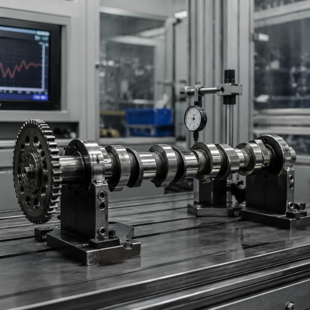
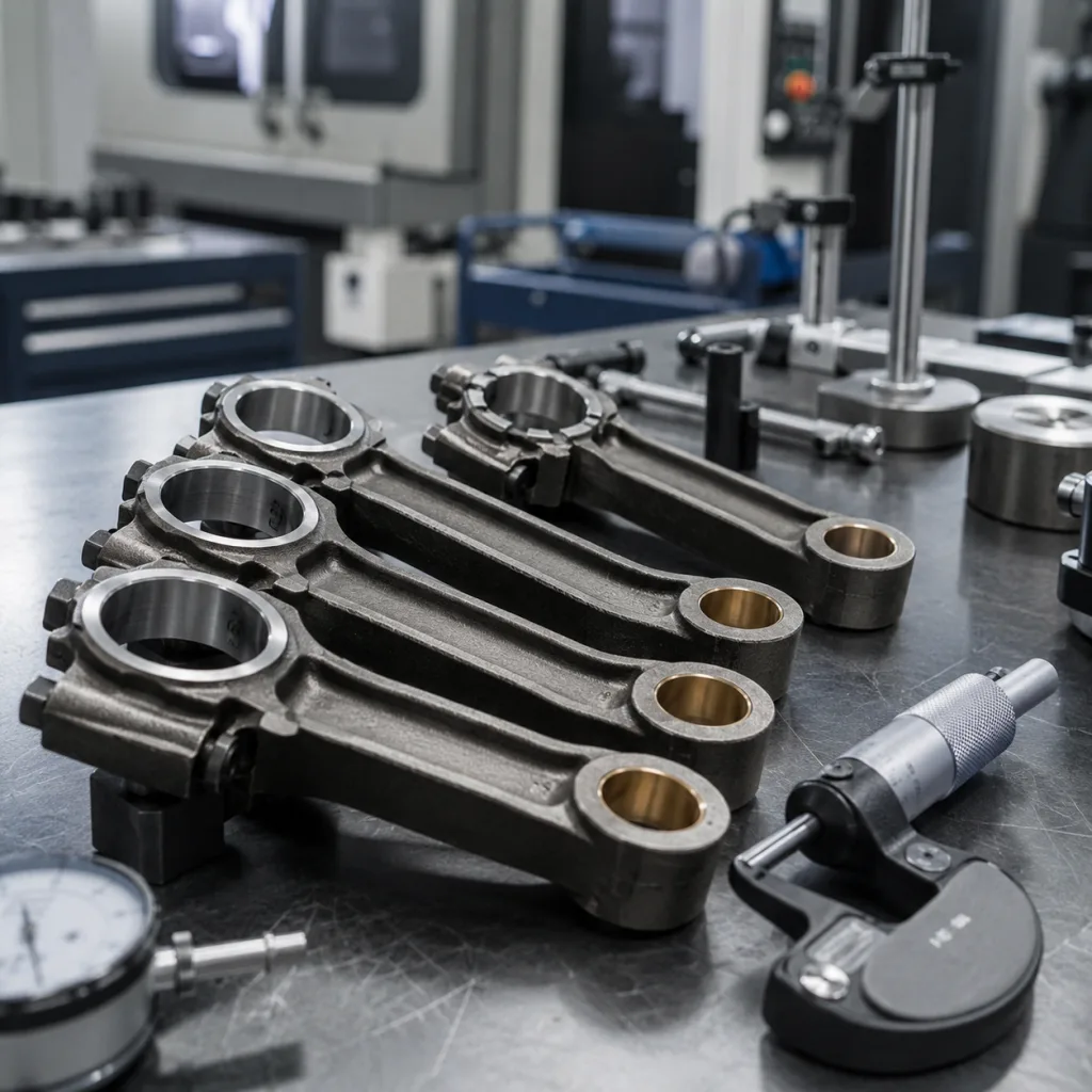
Camshaft for Mitsubishi Lancer Aftermarket Replacement Guide
A camshaft replacement for a Mitsubishi Lancer should be selected by engine code, lobe geometry, journal size, base-circle control, and sensor compatibility, not by brand claims alone. For procurement teams, the core question is whether the part matches the OE installation envelope and valvetrain requirement within production tolerances, and whether the supplier can document that match with measurable inspection data. Driventus supplies camshafts as an independent aftermarket manufacturer; brand names are referenced for fitment only. We build to documented inspection plans under IATF 16949:2016 and ISO 9001:2015, with traceability for raw material, machining, heat treatment, and final metrology. For buyers serving distributors, repair networks, or rebuilders, the main risk is dimensional drift that creates low oil pressure, valvetrain noise, incorrect cam timing, or sensor correlation faults. This article outlines the replacement criteria, validation checks, commercial terms, and sourcing points that matter before you place a production order or approve a trial shipment.
What a Mitsubishi Lancer replacement camshaft must match
For a camshaft for mitsubishi lancer aftermarket replacement, the minimum requirement is OE-equivalent fitment across the specific engine family being sourced. Mitsubishi Lancer applications vary by market, displacement, and valvetrain design, so the purchase spec should control the dimensions and interfaces that govern installation, timing, and service life.
Core dimensions and functional features to lock before ordering:
- Journal diameter and journal count, typically controlled within `±0.01 mm` on finished journal OD unless the drawing states otherwise
- Overall length and thrust-control features, commonly held within `±0.10 mm` on non-running datums
- Lobe lift, base-circle diameter, and lobe-to-lobe phase relationship, typically within `±0.03 mm` on lift-related dimensions for an OE-equivalent replacement
- Cam sensor trigger wheel location, tooth count, and phase angle, commonly validated within `±1° crank angle` or the customer’s OE reference tolerance
- Drive-end type: sprocket, gear, or timing pulley interface, including keyway width, bolt circle, and end-face runout
- Surface finish at journals and lobes, with journal roughness often targeted at `Ra ≤ 0.4 μm` and lobe contact surfaces controlled per application
If the engine uses hydraulic lash adjusters, a small change in lobe ramp rate can alter cold-start noise and idle stability. If the engine uses a cam position sensor, a dimensionally correct camshaft can still fail in service if trigger timing or sensor wheel phasing is out of spec. For that reason, Driventus treats these as measurable dimensional controls, not cosmetic details.
Fitment checks before you buy
A correct replacement order starts with the engine code, not just the vehicle model year. Mitsubishi Lancer applications differ by market and engine family, so buyers should verify the exact OE part number cross-reference before approving volume or releasing a toolless sample order.
Check these items on the sample or drawing:
- Confirmed OE reference, when the buyer already has a cited number; for example, a verified cross-reference such as `06A107065` only when supplied by the buyer’s application file
- Engine code, cylinder-head family, and valvetrain type
- Cam bore and journal alignment from the head drawing or a physical gauge check
- Lobe lift, base-circle diameter, and nose radius
- End play and thrust-surface width, typically controlled to `0.03–0.10 mm` depending on head design
- Timing sprocket keyway width, bolt pattern, and end-face perpendicularity
- Sensor wheel height, tooth count, and phase position relative to TDC
For mixed-market fleets, we recommend documenting VIN, engine code, and emission family on the purchase order. That reduces returns caused by selecting a visually similar camshaft from another Lancer variant and helps the supplier confirm the correct machining program before cutting production stock. For buyers comparing multiple quotes, require a dimensional report against the exact application drawing rather than relying on a catalog description alone.

Material, heat treatment, and surface quality
A camshaft used as a replacement part should be produced from the correct substrate and hardened to suit the application. In practice, buyers should ask for technical controls that translate into measurable wear resistance and stable machining performance.
| Parameter | Typical procurement check | Buyer acceptance target |
|---|---|---|
| Material | Alloy steel or cast iron, per drawing | Match the specified substrate and heat-treat route |
| Hardness | Controlled case or surface hardness, per spec | Commonly `55–62 HRC` on induction-hardened lobes, or the customer drawing requirement |
| Case depth | Effective hardened depth on lobes/journals | Often `0.8–2.0 mm`, depending on design |
| Runout | Measured at defined datum points | Typically `≤0.03 mm` on journals unless otherwise specified |
| Surface roughness | Journal and lobe finish recorded | Journal finish commonly `Ra ≤ 0.4 μm`; lobe surface per mating system |
| NDT / inspection | Cracks, porosity, or dimensional checks | 100% visual plus sampled magnetic-particle or penetrant inspection, if specified |