Camshaft Ford Replacement: OE-Match Checks That Matter
For a Ford camshaft replacement, the part has to match the engine, not just the vehicle model. Buyers should confirm journal diameter, lobe lift, base-circle geometry, timing phasing, surface finish, and heat-treatment consistency before release. Small deviations can change valve timing, idle quality, emissions behaviour, and bearing life. Driventus is an independent aftermarket manufacturer; brand names are referenced for fitment only. We support replacement programmes with dimensional control, traceable lots, and documentation aligned with IATF 16949:2016 and ISO 9001:2015. For procurement teams, the useful question is whether the part can repeat the OE function across batches, packaging formats, and regional supply routes. The sections below set out the checks that matter most when sourcing for distributors, repair chains, or OEM-linked programmes.
What a correct replacement must match
A reliable replacement is defined by function, geometry, and process control. For camshafts, the buyer should verify all of the following before approval:
- Journal diameter, roundness, and taper against the drawing or master sample.
- Lobe lift, base circle, and flank profile, not only the overall length.
- Nose hardness and case depth where nitriding, induction hardening, or surface finishing is specified.
- Sensor trigger features, keyways, and thrust faces where the engine uses variable valve timing.
- Packaging, rust protection, and oil-free handling for warehouse storage.
If you are building a line card, start with our catalog and the broader engine components range. For volume programmes, matching the visible shape is not enough. The part must pass the same dimensional window, fit the same followers and seals, and remain stable across repeat runs.
Sizing and surface control
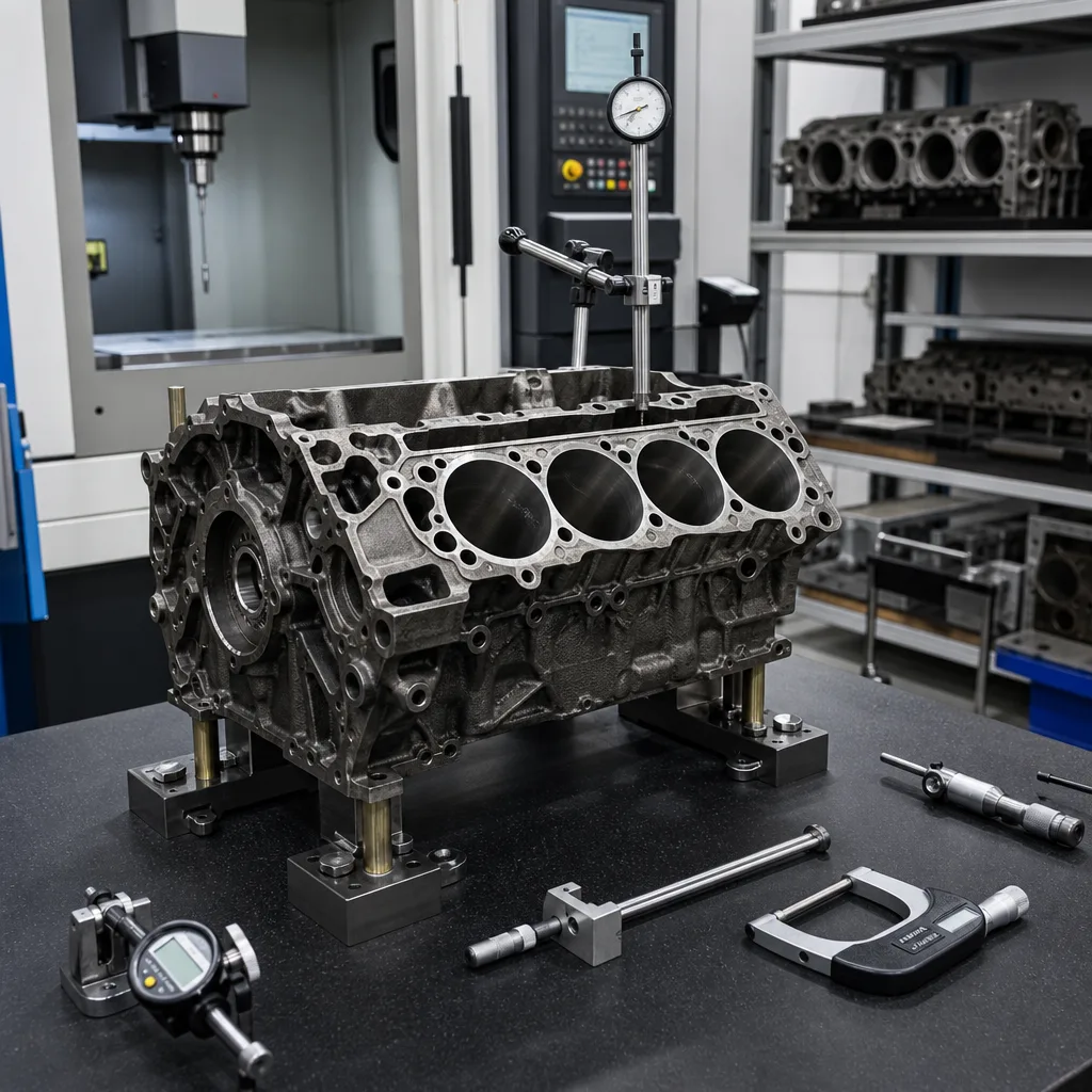
Most field failures on replacement camshafts come from control gaps in machining or heat treatment. Typical inspection points include ground journal finish, lobe profile, and concentricity between bearing surfaces and trigger features. On production programmes, a practical control pack often includes a CMM report, profilometer readings, hardness testing, and runout measurement between centres.
| Check point | What to verify | Why it matters |
|---|---|---|
| Journal size | Diameter, roundness, taper, and Ra finish | Protects the oil film and bearing life |
| Lobe profile | Lift, duration, flank shape, and phasing | Keeps valve timing within the calibration window |
| Surface hardness | Case depth and surface hardness, often 52-60 HRC depending on design | Reduces scuffing during break-in |
| Runout | Total indicated runout against the drawing limit | Prevents noise, wear, and timing variation |