Camshaft for Subaru Outback Replacement: OE-Match Checks
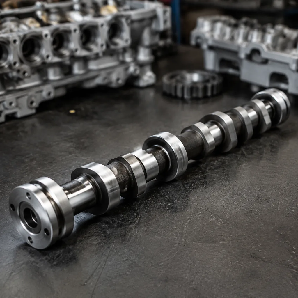
Choosing a camshaft for Subaru Outback replacement work starts with fit, profile, and validation—but the real decision is whether the part matches the engine, the operating context, and the sourcing risk you can tolerate. A camshaft that installs cleanly still fails if lobe timing, journal finish, trigger phasing, or oil-feed details drift from the original design. For procurement teams, the job is to separate visual similarity from true interchangeability, then prove the part can pass incoming inspection without rework. Driventus supplies aftermarket camshafts for engine programmes built to controlled dimensional targets and documented inspection routines. Driventus is an independent aftermarket manufacturer; brand names are referenced for fitment only. The sections below use a practical buyer’s lens: what to verify, where mismatches happen, what documents to demand, and how to compare options before you place the order.
Start with the engine code, not the model name
A camshaft for Subaru Outback replacement work should be selected by engine code first and model badge second. The same nameplate can cover multiple engines, and those engines may use different cam profiles, sensor triggers, and valvetrain hardware.
Use this order of checks:
- Confirm engine code from VIN data and the removed part
- Verify intake or exhaust position before quoting
- Match OE reference numbers only after engine family is known
- Check whether variable valve timing hardware is present
- Compare the sample against the original camshaft, not a catalog photo
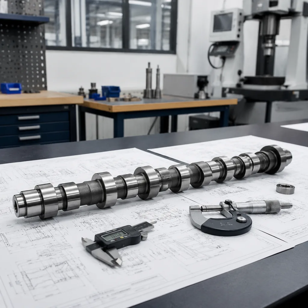
That sequence matters because model-year shortcuts create the most expensive sourcing mistakes. A 2.5L naturally aspirated unit, a turbocharged version, and later FB-series applications may share mounting cues while differing in lobe timing or phasing. Buyers should request the nominal spec set in writing: journal diameter to the nearest 0.01 mm, allowable runout, lobe lift tolerance, surface hardness, and any trigger-wheel location if fitted. If the supplier cannot state those values clearly, the fitment claim is not ready for procurement approval.
Where camshaft replacements usually go wrong
Most failures are not dramatic. They show up as noise, poor idle quality, or a comeback repair after installation.
Typical failure modes include:
| Failure mode | What causes it | |
|---|---|---|
| Excessive runout | Machining drift or poor shaft support | |
| Wrong base circle | Incorrect valve lash or timing behavior | |
| Trigger mismatch | Sensor fault, misfire, or hard start | |
| Incorrect end-play control | Noise and accelerated wear | |
| Poor surface finish | Oil-film loss and scuffing | |
| Mixed intake/exhaust use | Immediate drivability issues |
| Sourcing path | Best for | Tradeoff |
|---|---|---|
| Standard replacement | Known OE-referenced applications | Fastest route, least flexibility |
| OE-match sample build | Programs needing tighter validation | Requires more inspection detail |
| Custom profile | Non-standard or legacy applications | Longer approval cycle |