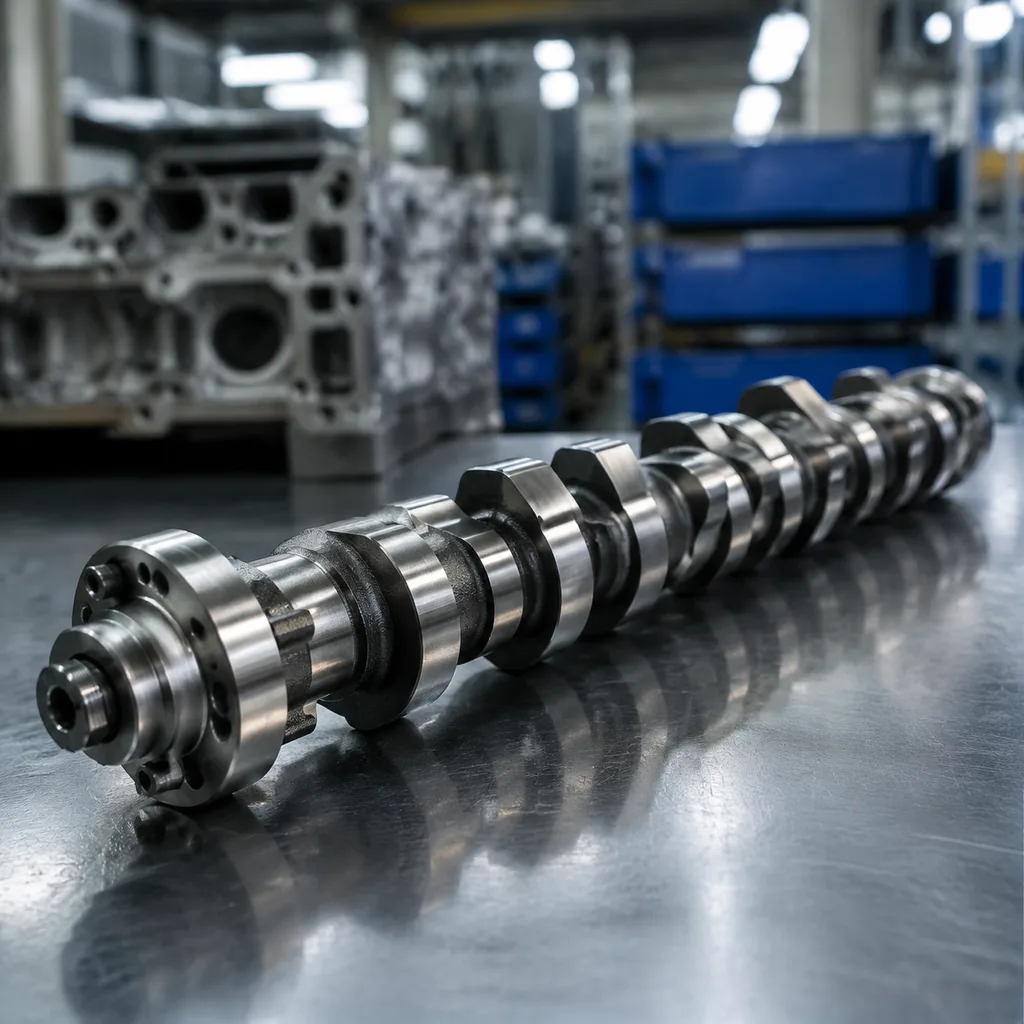
Camshaft for Mitsubishi Outlander Replacement: OE Match Guide
Choosing a camshaft for Mitsubishi Outlander replacement should start with the engine code, not the badge or model year. Across regions and generations, the Outlander nameplate has used several petrol and diesel engine families, with differences in cylinder-head layout, cam sensor targets, VVT/VVL systems, journal sets, thrust locations, and timing-drive interfaces. A shaft that looks right on the bench can still cause a no-start, cam/crank correlation fault, oil leak, tappet noise, or accelerated follower wear if the base circle, lobe phasing, trigger wheel, or phaser seat is wrong. This guide walks procurement teams through the checks that matter before approving a replacement camshaft: fitment by engine code and cam position, controlled dimensional inspection, material and heat-treatment evidence, corrosion-safe packaging, batch traceability, and validation records. Driventus is an independent aftermarket manufacturer; Mitsubishi and Outlander names are used only to identify fitment. For buyers in the EU, UK, US, Canada, Australia, Brazil, and other export markets, the B2B requirement is straightforward: the part must install without machining, preserve valve timing and oil-film stability, run quietly, protect journals and followers, and arrive with documentation your incoming QC team can use. Start with the engine code, then approve the finished camshaft against a drawing, OE sample, verified aftermarket sample, and the exact timing system used on the vehicle.
What must match on the Outlander engine
For a camshaft for Mitsubishi Outlander replacement, the engine code is the first control point. The Outlander range has used several petrol and diesel engine families depending on model generation and market, and the correct camshaft depends on the exact cylinder head, intake or exhaust position, timing drive, cam sensor strategy, and valve-control system. Catalogue images are not enough. Two shafts can share the same number of lobes and a similar overall length while differing in lobe centreline angle, trigger tooth offset, oil-feed position, dowel indexing, or thrust-face geometry.
Confirm these items before you compare price or lead time:
- Engine code, displacement, fuel type, and market version where available
- Intake or exhaust position on DOHC engines; some applications use non-interchangeable intake and exhaust cams
- SOHC, DOHC, MIVEC/VVT, or other variable-valve-control configuration
- Number of lobes, lobe sequence, lobe handedness, and orientation along the shaft
- Journal diameter, journal width, journal count, and overall shaft length
- Thrust face location, thrust-plate or cap interface, and specified end-float control method
- Seal land diameter, surface finish, lead-in chamfer, and oil-slinger detail where applicable
- Cam sensor target arrangement: tooth count, tooth width, air-gap face, angular offset, and orientation
- Timing drive interface: sprocket seat, phaser seat, keyway, dowel pin, bolt thread, locating face, or timing slot
- Oil feed holes, annular grooves, cross-drillings, and lubrication-path alignment to the cylinder head
- Hydraulic lash adjuster, roller follower, or bucket/tappet contact requirements if profile or surface finish differs
Model year alone is unreliable because mid-cycle engine changes, regional emissions packages, and superseded part numbers can create catalogue overlap. Use a three-point fitment check: VIN or registration decode, engine plate/code confirmation, and physical comparison with the old camshaft or a verified sample. For repeat buying, record the cam position, timing system, OE or aftermarket reference, drawing revision, and whether the order is approved from an original sample or a production validation lot. That simple discipline prevents a common B2B failure: receiving a camshaft that drops into the cylinder head but does not match the ECU’s cam signal, the phaser indexing, or the engine’s valve timing geometry.
Dimensional checks that prevent receiving failures
Receiving failures often trace back to one uncontrolled feature, not an obvious visual defect. A replacement camshaft can pass an appearance check yet still cause low hot-idle oil pressure at the bearings, noisy valve operation, P0016/P0017-type cam/crank correlation faults, hard starting, seal leakage, or rapid lobe wear if a critical dimension sits outside the approved tolerance. Ask the supplier to confirm the finished component against a controlled drawing or a golden sample with defined inspection points, rather than relying only on a catalogue interchange number.
Typical drawings define camshaft dimensions in hundredths or thousandths of a millimetre, depending on the feature. The exact tolerance must follow the application drawing, but the inspection plan should at minimum capture the items below.
| Check | What to confirm | Why it matters | |
|---|---|---|---|
| Journal diameter | Measured at specified axial positions and at 90° intervals on each bearing journal | Controls bearing clearance, oil-film stability, oil pressure, and hot idle noise | |
| Journal width | Width, shoulder position, edge radius, and relief at each bearing position | Prevents cap drag, bearing edge loading, and local seizure | |
| Overall length | End-to-end length, thrust-face distance, nose length, and rear-end machining | Prevents axial load, cover interference, sprocket misalignment, and seal offset | |
| Lobe lift | Intake or exhaust lobe height minus base circle at defined measuring planes | Keeps valve lift, engine breathing, and cylinder balance consistent | |
| Base circle | Diameter, roundness, and concentricity relative to the journal axis | Protects valve lash, hydraulic follower preload, and idle quality | |
| Lobe phasing | Angular relationship between each lobe centreline and the timing reference | Maintains valve timing, emissions behaviour, and cylinder-to-cylinder consistency | |
| Trigger pattern | Tooth count, tooth width, angular offset, target face runout, and orientation | Avoids cam sensor errors, misfire codes, and no-start conditions | |
| Sprocket or phaser seat | Pilot diameter, locating face runout, keyway/dowel position, thread, and bolt-seat detail | Keeps timing hardware seated, indexed, and clamped correctly | |
| Seal land | Diameter, roundness, surface finish, lead-in chamfer, and scratch control | Prevents oil leakage and premature radial seal wear | |
| Oil holes and grooves | Hole diameter, angular position, burr removal, and groove alignment | Maintains lubrication to journals, phasers, and cam caps where applicable | |
| Runout/straightness | Total indicator reading on specified journals or centres after final machining | Reduces bearing stress, vibration, and uneven follower contact |
| Option | Best use | Main risk | Buyer action |
|---|---|---|---|
| OE-equivalent new part | Routine service, distributor stock, planned maintenance, and active applications | Low if drawing match, timing geometry, material controls, and lot traceability are verified | Ask for dimensional data, material/heat-treatment records, first article evidence, and packaging specification |
| Remanufactured core | Older or low-volume applications with limited new supply | Core fatigue, mixed prior service history, reduced lobe height, variable base circle, and uncertain hardness after regrinding | Require crack inspection, grind-limit records, lift/base-circle data, hardness checks, straightness checks, and core traceability |
| Custom profile | Fleet programmes, regional engine variants, motorsport/off-road use where applicable, or hard-to-source engine codes | Longer approval cycle, profile validation requirement, and risk of emissions or drivability mismatch if not engineered correctly | Use custom manufacturing with sample parts, timing references, follower data, target measurements, and trial-fit feedback |


